Have you thought about who turns on and off those street lights on the road? Turning on and off those street lights may be a boring task. We can make this process automatic by a simple automatic street light circuit. Also, you can automate your home lighting, lights in the garden, and other outside places automatically by using this simple automatic light circuit. Let’s see how to make automatic street light with circuit diagram.
This automatic street light circuit will automatically turn ON and OFF the lights. It will not only save your time but also saves electricity and indirectly the environment. You need not worry about turning lights on and off anymore. Also, you can control those lightings manually.
So let’s head on to the circuit. First of all, we need some components, LED, resistor relay, and IC.
Street Light Circuit:
Circuit components:
- LM 741 or LM 358 opamp
- 1 LED
- Relay – 5V
- Resistors 1kΩ
- Preset 10k ohm
- 1x 330-ohm resistor
- BC547 transistor
- 1 LDR (light dependent resistor)
- Any bulb of your choice
- Wire
- PCB board
- Power supply or battery pack.
Street Light Circuit explanation:
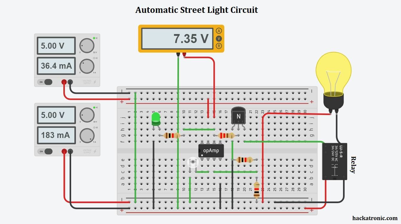
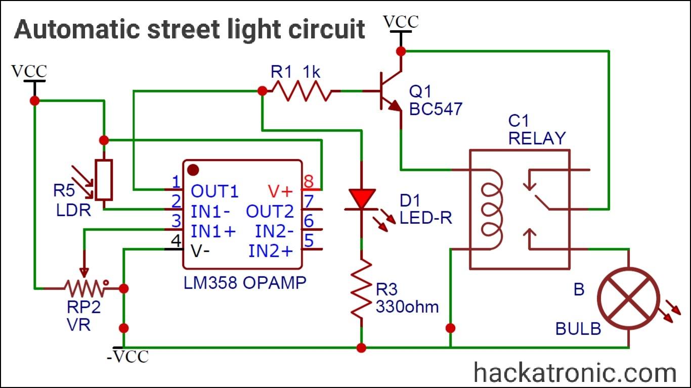
Pin number 7 of the opamp is connected to the Vcc and pin 4 is grounded. Pin 3 is the non-inverting terminal and pin 2 is the inverting terminal. A potentiometer is connected to the 3rd terminal of the opamp and LDR is connected to the inverting terminal of the opamp. The output of the opamp is given to a relay circuit. This relay circuit will drive a bulb.
If you use LM741 IC you need a dual power supply. You can also use LM358 opamp. The output of opamp is given to BC 547 transistor, this transistor drives the relay circuit. A high-power bulb is connected to the relay. The output of the opamp drives a 5V relay which will turn ON the AC circuit making the bulb glow.
Working of the automatic street light circuit:
This automatic lighting Circuit works on the opamp comparator principle.
Read this article to understand the working of opamp as a comparator.
The potentiometer connected at the non-inverting terminal of the opamp is used to set threshold voltages. And LDR connected at the inverting terminal of the opamp. The LDR creates a voltage at the inverting terminal. Since the resistance of the LDR is dependent on the intercity of light falling on it, its output voltage is controlled by the intercity of light. The opamp compares the voltage at its input terminal and produces output voltage at pin number 6.
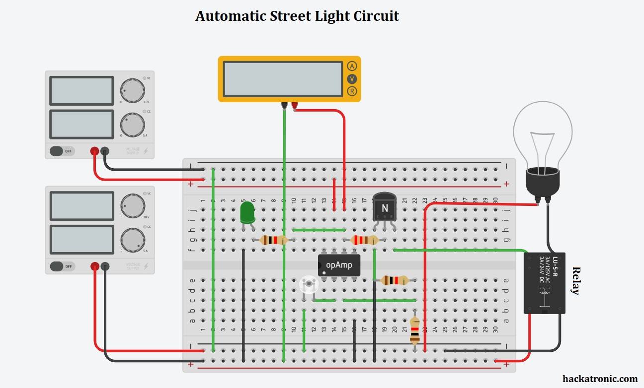
In daytime due to the light output of the LDR is high. When the output voltage of LDR is less than the threshold voltage output of the opamp is Low. Hence the relay circuit is OFF during daytime. At night, when the output of LDR is Low the output of the opamp is High which makes the relay circuit ON. So the lights will stay off in the daytime. This circuit will automatically turn on the light as soon as sun rays falling on LDR will go low and darkness occurs.
Conclusion:
This automatic street light circuit is a great project to save power, environment, energy, and money, making our life easier and comfortable.
3 Simple IR Proximity Sensor Circuits with Working & Applications
Zero Crossing Detector Circuit Working, Waveform & Applications

Can u please tell which resistors is 10k ohm and which is the preset resistor of 330 ohm
1KΩ is at base of transistor, and 330Ω connects to LED.