The MAX485 TTL to RS485 Modus Module is a popular RS-485/RS-422 transceiver chip manufactured by Maxim Integrated. It’s commonly used in applications where long-distance serial communication is required, such as industrial control systems, building automation, and instrumentation.

MAX485 Modbus Module:
A MAX485 module typically includes the MAX485 chip along with necessary support components like voltage regulators, termination resistors, and connectors. These modules make it easier to incorporate RS-485 communication into projects as they provide a convenient interface for microcontrollers or other devices.
Overview of MAX485 Module:
- MAX485 Chip: The heart of the module, it’s responsible for converting between the UART signals of the microcontroller and the differential signals required for RS-485 communication.
- Voltage Regulators: MAX485 operates at a higher voltage (usually 5V), but RS-485 communication lines might operate at different voltage levels. Voltage regulators ensure proper voltage levels for both the chip and the communication lines.
MAX485 TTL to RS485 Module - Termination Resistors: RS-485 communication lines typically require termination resistors to minimize reflections and ensure signal integrity, especially in long-distance communication.
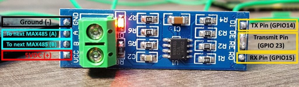
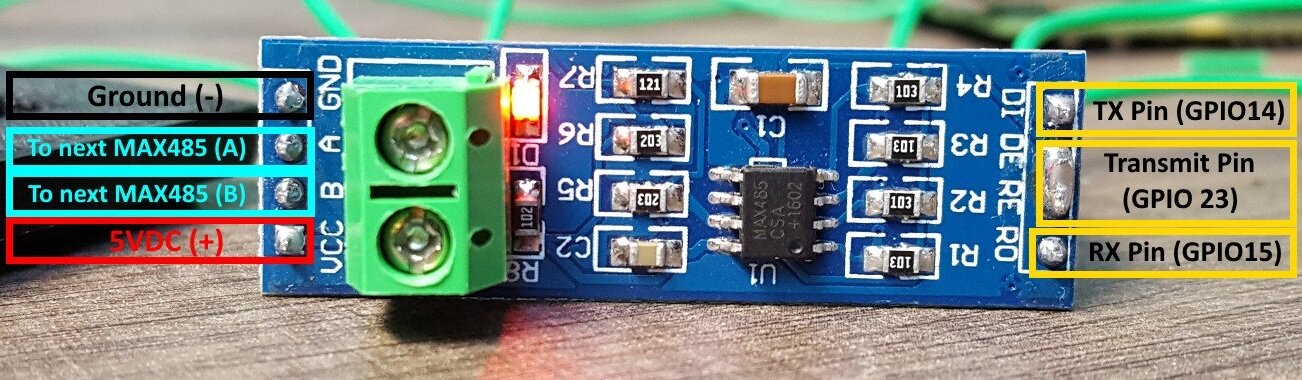
- Connectors: These modules usually come with connectors for easy connection to other devices. They may include terminal blocks, RJ45 connectors, or pin headers.
- Driver/Receiver Circuitry: MAX485 includes both driver and receiver circuitry necessary for bidirectional communication over the RS-485 bus.
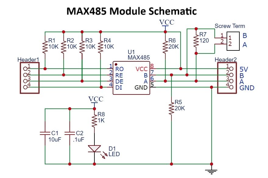
MAX485 Module Schematic - Direction Control Pins: MAX485 modules often include control pins to manage the direction of communication (receive or transmit) between the microcontroller and the RS-485 bus.
- LED Indicators: Some modules feature LEDs to indicate power and communication activity, aiding troubleshooting.
When using a MAX485 TTL to RS485 module, you typically connect it to a microcontroller or other devices via UART. You’ll also need to connect the RS-485 lines to the network you want to communicate with. Finally, you’ll configure the direction control pins to switch between transmit and receive modes as needed.
Overall, MAX485 modules simplify the implementation of RS-485 communication in projects by providing a ready-made interface with necessary support components.

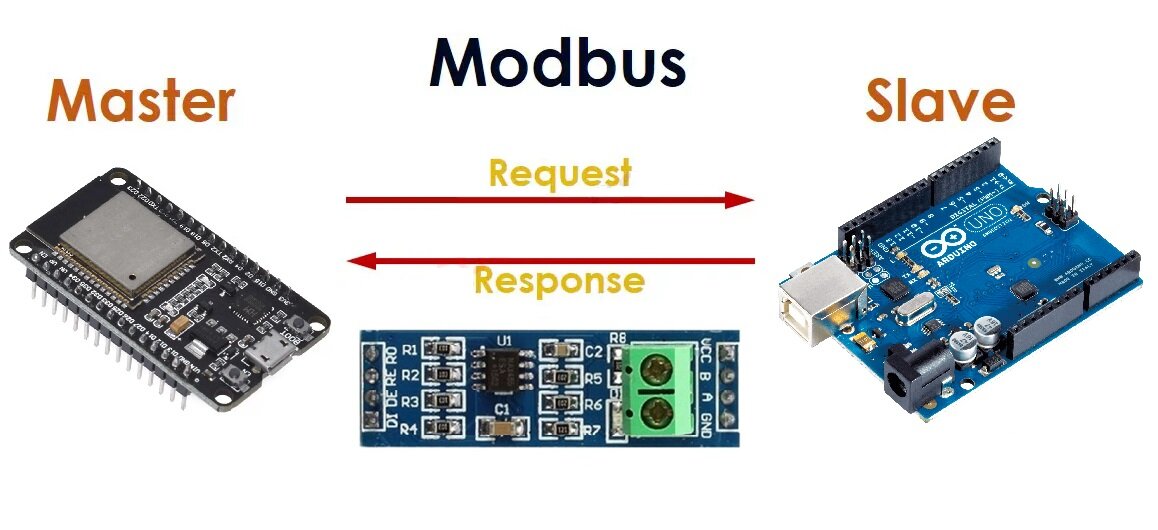
Implementing Master Slave Modus Communication by ESP32 and Arduino:
To implement Master Slave communication using ESP32 and MAX485, you’ll need to set up the ESP32 as the Master and the MAX485 as the Slave. Here’s a basic example using Arduino code:
Master Code (ESP32):
#include <SoftwareSerial.h>

#define RX_PIN 16 // ESP32 RX pin
#define TX_PIN 17 // ESP32 TX pin
#define DE_PIN 2 // MAX485 DE pin
#define RE_PIN 3 // MAX485 RE pin

SoftwareSerial mySerial(RX_PIN, TX_PIN); // RX, TX

void setup() {
Serial.begin(9600);
mySerial.begin(9600);
pinMode(DE_PIN, OUTPUT);
pinMode(RE_PIN, OUTPUT);
digitalWrite(DE_PIN, HIGH);
digitalWrite(RE_PIN, HIGH);
}

void loop() {
digitalWrite(DE_PIN, HIGH); // Set DE pin high for transmitting
digitalWrite(RE_PIN, HIGH); // Set RE pin high for receiving
mySerial.println("Hello from ESP32");
delay(1000);
}
Slave Code (Arduino):
#include <SoftwareSerial.h>

#define RX_PIN 2 // MAX485 RX pin
#define TX_PIN 3 // MAX485 TX pin
#define DE_PIN 4 // MAX485 DE pin
#define RE_PIN 5 // MAX485 RE pin

SoftwareSerial mySerial(RX_PIN, TX_PIN); // RX, TX

void setup() {
Serial.begin(9600);
mySerial.begin(9600);
pinMode(DE_PIN, OUTPUT);
pinMode(RE_PIN, OUTPUT);
digitalWrite(DE_PIN, LOW);
digitalWrite(RE_PIN, LOW);
}

void loop() {
if (mySerial.available()) {
String message = mySerial.readString();
Serial.println("Received: " + message);
}
}
Wiring of ESP and Arduino with MAX485:
Also, connect the DE and RE pins of the MAX485 together and connect them to a GPIO pin on the Arduino and ESP32 (e.g., GPIO 2 and 3 as in the code above).
Connect VCC and GND of both modules accordingly.
Explanation:
- The Master (ESP32) sends a message “Hello from ESP32” repeatedly.
- The Slave (Arduino with MAX485) waits for messages from the Master and prints them to the Serial Monitor.
Remember, you might need to adjust pin assignments based on your specific hardware configuration.
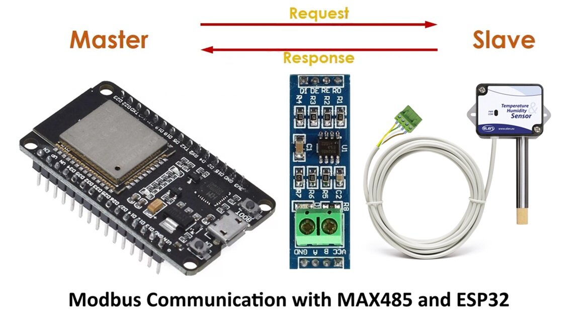
Modbus RTU communication using ESP32 and Temperature Sensor:
Here we have implemented Modbus to read data from a Modbus RTU device over RS485 using an ESP32.
Connect ESP32 and MAX485 TTL to RS485:
- TX (transmit) pin of ESP32 to MAX485 DI (data in).
- RX (receive) pin of ESP32 to MAX485 RO (receive out).
- ESP32 GPIO pin 16 to MAX485 DE (driver enable) and RE (receiver enable) pins.
- Connect the MAX485 VCC pin to a 5V power source and GND pin to GND.
- Connect MAX485 to the RS485 network.

Install Libraries:
You’ll need to install the ESP32 core for Arduino IDE and SoftwareSerial library.
#include <SoftwareSerial.h>

#define TX_PIN 19
#define RX_PIN 18
#define DE_RE_PIN 4
#define LED_PIN 2

SoftwareSerial Soft_Serial(RX_PIN, TX_PIN);

byte incomingByte[9] = {0};
byte no_Byte = 0;

// Modbus Request Bytes
byte sendBuffer[] = {0x01, 0x03, 0x00, 0x01, 0x00, 0x01, 0xD5, 0xCA}; // Single Read for Temperature
// Modify this array to change the request

float humidity, temperature;

void setup() {
Serial.begin(115200);
Soft_Serial.begin(9600);

pinMode(DE_RE_PIN, OUTPUT); // DE/RE Control pin of RS-485
pinMode(LED_PIN, OUTPUT);
digitalWrite(LED_PIN, HIGH);

Serial.println("\n\nWelcome to JP Learning\n");
}

void loop() {
read_Modbus();

if (no_Byte >= 7) {
if (parseData()) {
if (no_Byte == 9 && incomingByte[1] == 3) {
humidity = parseTemperatureHumidity(3);
Serial.println("\nHumidity = " + String(humidity, 2) + " %\n\n");
} else if (no_Byte == 9 && incomingByte[1] == 4) {
temperature = parseTemperatureHumidity(3);
Serial.println("\nTemperature = " + String(temperature, 2) + " °C\n\n");
}
}
no_Byte = 0;
}
delay(5000);
}

void read_Modbus() {
digitalWrite(DE_RE_PIN, HIGH); // DE/RE=HIGH Transmit Enabled

Soft_Serial.write(sendBuffer, sizeof(sendBuffer));

digitalWrite(DE_RE_PIN, LOW); // DE/RE=LOW Receive Enabled

while (Soft_Serial.available() > 0 && no_Byte < 9) {
incomingByte[no_Byte++] = Soft_Serial.read();
}
}

bool parseData() {
return no_Byte >= 7 && incomingByte[0] == 0x01; // Check minimum data length and slave address
}

float parseTemperatureHumidity(int start) {
int value = incomingByte[start] << 8 | incomingByte[start + 1];
return float(value) / 10;
}
Working of the Code:
Explanation of how the code is working. Let’s break down how the code works:
Hardware Setup:
- The ESP32 is connected to the RS485 transceiver (MAX485) via Software Serial.
- GPIO pin 4 is used to control the DE (Driver Enable) and RE (Receiver Enable) pins of the RS485 transceiver.
- Another GPIO pin is used to control an LED, which could indicate various statuses of the system.
Software Setup:
- The code begins by including necessary libraries and defining pin assignments.
Initialization:
- Inside the
setup()function, serial communication is initiated for debugging purposes. - SoftwareSerial is configured with the specified pins and baud rate.
- DE/RE and LED pins are set as outputs, and the LED is turned on.
Main Loop:
- The
loop()function continuously reads data from the Modbus RTU device in intervals of 5 seconds.
Reading Modbus Data:
- The
read_Modbus()function is responsible for initiating the Modbus request, receiving the response, and storing it in theincomingBytearray. - It enables transmission by setting DE/RE pin to HIGH, sends the Modbus request, then switches to receive mode by setting DE/RE pin to LOW.
- While data is available on the SoftwareSerial buffer, it’s read byte by byte and stored in the
incomingBytearray until a complete response is received.
Data Parsing:
- The
parseData()function checks if the received data is valid and interpretable. It verifies the slave address and minimum data length. - The
parseTemperatureHumidity()function extracts temperature or humidity values from the Modbus response, depending on the function’s parameterstart.
Displaying Data:
- Once a valid Modbus response is received and parsed, the temperature or humidity value is displayed on the Serial monitor.
- If the Modbus function code is 3 (read holding registers), it interprets the data as humidity.
- If the function code is 4 (read input registers), it interprets the data as temperature.
Explanation of the Modbus Request:
- The
sendBufferarray contains the Modbus request bytes. - The request is sent out to the Modbus RTU device to request data.
- It specifies the device address, function code, register address, and number of registers to read.
Explanation of Modbus Response:
- The Modbus response is received in a byte-wise manner.
- The response includes the slave address, function code, and data.
- The data section contains the requested information (temperature or humidity).
LED Indication:
- The LED is used as an indicator. It’s turned on initially and can be used for various purposes such as indicating system activity or status.
Delay:
- After each data reading and processing cycle, there’s a delay of 5 seconds (
delay(5000)) before the next cycle begins.
That’s the breakdown of how the code works! It essentially sends a Modbus request to the slave device, receives the response, parses the data, and then displays it.
Testing Modbus Communications:
- Upload the code to your ESP32.
- Connect your ESP32 to the Modbus network and verify connections.
- Monitor the serial output to see if the communication is successful.
MAX485 Module Applications:
Industrial Automation:
- Modbus Communication: MAX485 is commonly used for implementing Modbus communication in industrial automation systems where long-distance communication and noise immunity are essential.
- Fieldbus Networks: It’s used for connecting sensors, actuators, and other devices in fieldbus networks like PROFIBUS, DeviceNet, and others.
Building Automation:
- HVAC Control Systems: MAX485 is used for communication between temperature sensors, actuators, and HVAC controllers in heating, ventilation, and air conditioning systems.
- Lighting Control Systems: It’s used for controlling and monitoring lighting systems in smart buildings.
Data Acquisition Systems:
- Data Loggers: MAX485 facilitates communication between data loggers and remote sensors or monitoring equipment, enabling data collection from multiple points.
- Remote Monitoring Systems: It’s used in systems that monitor parameters like temperature, pressure, or flow remotely.
Renewable Energy Systems:
- Solar Panel Monitoring: MAX485 can be used to communicate with solar panel inverters, charge controllers, and energy meters in solar power systems.
- Wind Turbine Control: It’s utilized in communication systems for monitoring and controlling wind turbines in wind energy installations.
Access Control and Security Systems:
- Access Control Systems: MAX485 can be used for communication between access control panels, card readers, and other security devices in access control systems.
- CCTV Systems: It’s used in CCTV systems for communication between cameras, DVRs, and control centers.
Automotive Applications:
- On-Board Diagnostics (OBD): MAX485 can be used in vehicle diagnostic systems for communication between the OBD port and diagnostic equipment.
- Vehicle Telemetry Systems: It’s used for communication in vehicle telemetry systems, such as monitoring vehicle parameters in fleet management.
Environmental Monitoring:
- Environmental monitoring systems often use RS485 for connecting sensors measuring parameters like temperature, humidity, air quality, and water quality.
- The MAX485 module allows data to be transmitted over long distances in outdoor environments with minimal signal degradation.
Other Applications:
- Robotics: MAX485 is used for communication between different components of robotic systems, such as motors, sensors, and control units.
- Telemetry Systems: It’s used in telemetry systems for monitoring and controlling remote equipment in various industries.
In summary, MAX485 TTL to RS485 module is versatile and finds applications in various fields where reliable, long-distance communication is required, especially in noisy industrial environments.