here are the Top 5 DIY bc547 transistor projects for you. Bc-547 is an NPN bipolar junction transistor(BJT). It is widely used for power amplification and switching. The word transistor means two words, transfer and resistor. The use of a transistor is to transfer the resistance.
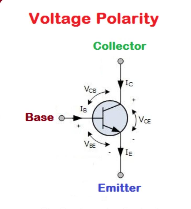
In transistors, a small amount of current at the base terminal controls a larger amount of current at the emitter and collector.
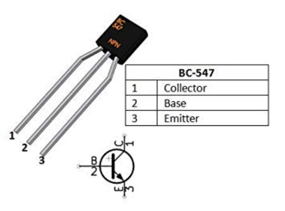
BC547 has three terminals as in other transistors.
1. collector terminal
2. base terminal and
3. emitter terminal respectively.
The current flowing from the base to the emitter controls the current flowing through the collector.
BC547 is usually used for amplification and switching purposes.
The maximum current gain of this transistor is around 800.
Supplying a proper DC voltage to the transistor is known as the biasing of the transistor. For proper operation of the transistor, A fixed DC voltage is required. It is best operated in the active region.
BC547 is biased in such a way that it is partially on for all the applied inputs. The inputted signal is amplified at the base and then gets transferred to the emitter.
Working principle:
When the input voltage is applied at emitter and base terminal, some amount of current starts to flow from base to the emitter which controls the current at the collector terminal. To use Bjt as an amplifier, emitter-base junction is forward biased whereas the collector-base junction is reverse biased.
Here are top 5 bc547 transistor projects:
bc547 transistor project no 1
Bc547 transistor (an NPN bipolar junction transistor(BJT)) can be used for audio amplification. However, this never works properly and output is not good.
An amplifier is an electronic circuit or device which is used for amplification and switching purpose. It is widely used in the electronic industry. There are many types of amplifiers available in the market, but you can make an amplifier using very little components and money. In this project, we will make a Simple audio amplifier Circuit using a BC547 NPN transistor.
Components Required:
- Transistor BC547
- Bread Board
- 4 to 8 Ohm Speaker
- 100uF capacitor
- 5V to 9V DC supply
- Resistor 1k to 2.2k
- Aux wire or MIC
- Connecting wires

Circuit Diagram:
The Circuit diagram for the amplifier of the AUX output of the Mobile Phone is as shown:
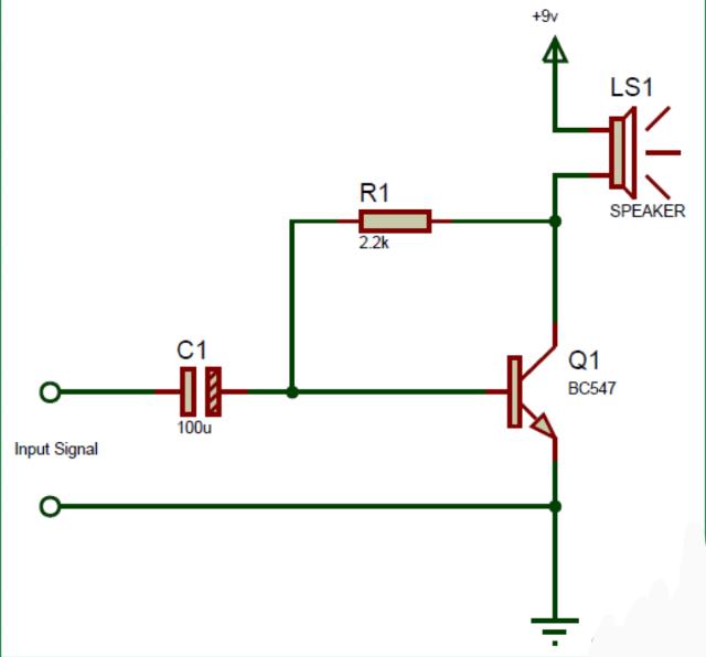
This is the simplest circuit for an amplifier
Here the capacitor C1 is a coupling capacitor. It is used as a filter to block out the DC component of the input signal.
In this circuit, the transistor allows a larger current to flow when we apply smaller voltage at its base.
we are applying a voltage at its base from the audio input signal by AUX cable. Due to this larger current from the 9v battery? passes thought the speaker. In this way, it converts Electric energy into the audio output.
the amplification of the input signal from MIC:
Here we have placed a MIC in place of the AUX jack. The circuit will amplify the voice input fed by the condenser mic.
2.)bc547 transistor project- Simple fire detection system:
The second application is a simple fire detector.
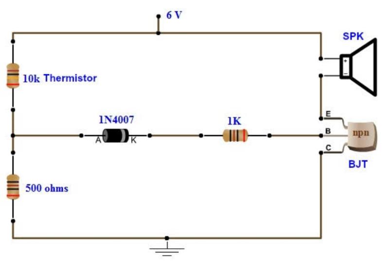
Here is a very simple Temperature Sensor Circuit or Heat Sensor Circuit. This circuit requires fewer easily available components. This Heat Sensor is very simple and effective.
Components:
Transistor BC547 is used as a Heat Sensor, As the temperature of the PN junction increase, the transistor starts conducting.
Diode 1N4148 and a variable resistor of 1k ohm is used to set a threshold level for the sensitivity of heat. the sensitivity of the circuit is adjusted by rotating the knob.
Working:
working of the circuit is very simple when the temperature increases to the level that crosses the threshold value set by the Potentiometer, the collector current increases, and the LED starts illuminating slowly.
We can use a Buzzer also in place of an LED. Set the Potentiometer at the position, where a slight rotation will start a dim illumination in LED.
The temperature dependency of a transistor can be understood by the formula presented here. The Base-Emitter voltage (VBE) drops approx. -2.5 mV/°C.
The operating temperature of the BC547 Transistor is up to 150 degrees C, so it can be perfectly used at high temperatures as a Heat Sensor. we can easily make a Fire Alarm out of it.
3.) bc547 transistor project -Alarm Circuit
This is a simple alarm circuit in the bc547 transistor project.
Latches are used frequently in alarm circuits. If they are triggered once, the sirens or buzzer will sound indefinite until someone manually turns it off.
In this circuit, we will use 2 transistors, the BC547, and the BC557 to make a latch.
Components required:
- BC547 NPN transistor
- BC557 PNP transistor
- 2 2.2KΩ resistors
- 1KΩ resistor
- Buzzer
- Power supply
The BC557 is a BJT PNP transistor.
It can handle a maximum voltage of 65V at its emitter.
The resistors are used for biasing purposes.
In this circuit, we will latch on a buzzer.
Circuit diagram:
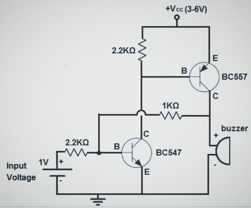
In this circuit, the first transistor is the BC547, and second is the BC557.
The 2.2KΩ resistor at the top of the circuit will limit the current going into the base of the BC557 transistor.
The 1KΩ resistor is used to limit current going into the base of the BC547 from the output of the BC557.
There are 2 currents fed into the base of the BC547 transistor. There is the current produced from the input voltage source Vin.
current is fed into the BC547 from the output of the BC557. The first current from the input voltage source is needed to trigger the latch circuit to on. And the current from the output of the BC557 going the BC547 is needed to keep the circuit latched on.
The BC547 provides a continuous current to the base of the BC547 so that it can stay continuously on.
The 2.2KΩ resistor limits current to the base of the BC547 from the input.
The buzzer is at the output of the circuit.
Working of the circuit:
When 0.65V is fed into the base of the BC547 transistor to turn it on. When it turns on, current flows from VCC down to the base of the BC557 transistor. This, in turn, turns on the BC557 transistor. Current now flows from the collector of the BC557 in 2 directions.
Some of the current flow to turn on the buzzer. And some into the base of the BC547 transistor. This is how the latch is formed. When we turn on the BC547 it turns on the BC557.
Then the BC557 provides continuous current to the base of the BC547 so it remains on even if we turn off the input voltage supply. The only way to turn off the circuit is to turn off the supply voltage VCC. Turning off the input voltage VIN will cause no effect. Input voltage is once needed to turn on the latched.
So this is how a latch circuit can be built using transistors.
It perfectly resembles an SCR(silicon-controlled rectifier).
It functions as a digital latch. So this is how alarm circuit works.
4.) bc547 transistor project – transistor-switch circuit:
It can also be used as a switch.
we use an NPN transistor 547 to control a high-power LED as shown below.
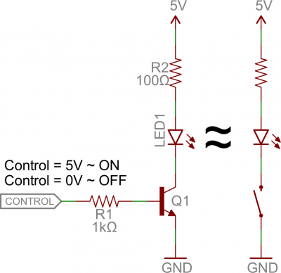
Our control input goes to the base, the output is the collector and emitter is kept at a fixed voltage.
While a normal switch would require an actuator to be physically flipped. This switch is controlled by the voltage at the base pin. A microcontroller I/O pin, like Arduino can be programmed to go high or low to turn the LED on or off.
When the voltage at the base is greater than 0.6V the transistor starts saturating and becomes a short circuit between collector and emitter. When the voltage at the base is less than 0.6V the transistor is in cutoff mode and no current flows because it is an open circuit between C and E.
5.)LED Flasher Using BC547 and BC557 Transistors
Here is one more bc547 transistor project, it’s an LED flasher. Also known as an LED blinking circuit. students use a 555 timer IC to build a simple LED blinker, which is fine but not cost-effective to dedicate an IC permanently for such an easy task. we can use cheaper components to blink LEDs. Also, you can make permanent blinkers on stripboard, after building a prototype on a breadboard.
Circuit Operation
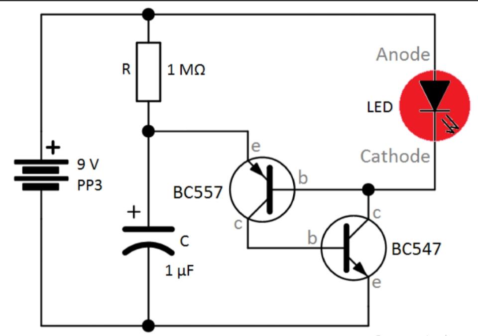
This circuit uses a BC557 PNP transistor connected to a BC547 NPN transistor in such a way that the BC547 conducts for a very long time making the LED light. The resistor R, and Capacitor C, determine the timing of the flasher, and its period is proportional to R × C.
The capacitor C charges through the resistor R very slowly since its value is 1-MΩ. When the capacitor has sufficient charge, it discharges through the emitter junction of the BC557 transistor. This charge flows through the base junction of BC547 making it conduct which powers the LED. To understand the operation you need to understand basic transistor switching theory. A positive voltage at the base junction of an NPN transistor will cause it to conduct. Whereas PNP transistor requires a negative or zero volts at the base to conduct.
use a general-purpose low power LED(with series resistance) for low power consumption. Use a 9V DC battery.

Best site for learning thanks