In this project, we will use the MQ2 Gas sensor circuit to detect Methane, Butane, LPG, Smoke which is released into the environment at the time of the gas leak. MQ2 Gas sensor circuit diagram is as shown in the figure. MQ2 gas sensor can sense butane, LPG, Smoke, Alcohol, Propane, Hydrogen, Methane and Carbon Monoxide.
Gas leakage is a very dangerous situation it can cause breathing problems, headache, and other physical problems. A gas leak can cause really very big fire, blasts, loss of lives, and big property damage at places where gases are used for either cooking or other commercial purposes.
MQ2 Gas sensor:
MQ2 sensor is a 6-pin semiconductor device that sense gas and smoke. It is round and somewhat pyramid-like having a base on which the sensor is mounted and a protective forged.
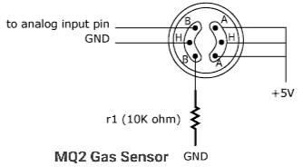
It has three pairs of pins namely A, B, and H pin. The H pins are connected to the supply voltage. A and B pins are interchangeable. one pin is connected to pulled to the ground using a resistor and the other act as an analog output pin.
To use this sensor simply connect all three pins at one side to +Vcc. On the other side connect the first pin to the ground via a resistor. Connect the middle pin to the ground and the remaining pin is the output pin.
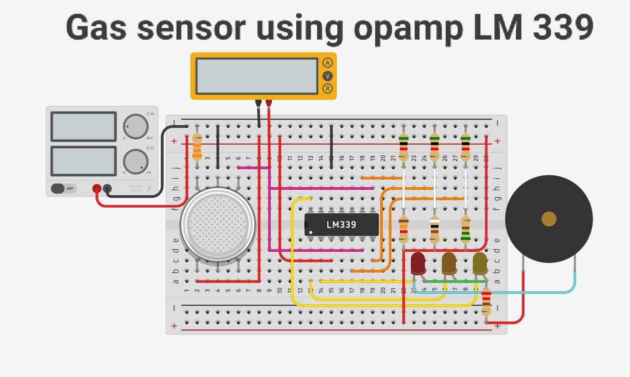
A simple gas sensor and alarm circuit are as shown in the figure. We can use any gas sensors like MQ2, MQ6. In this project, we are using the LM339 quad opamp comparator IC.
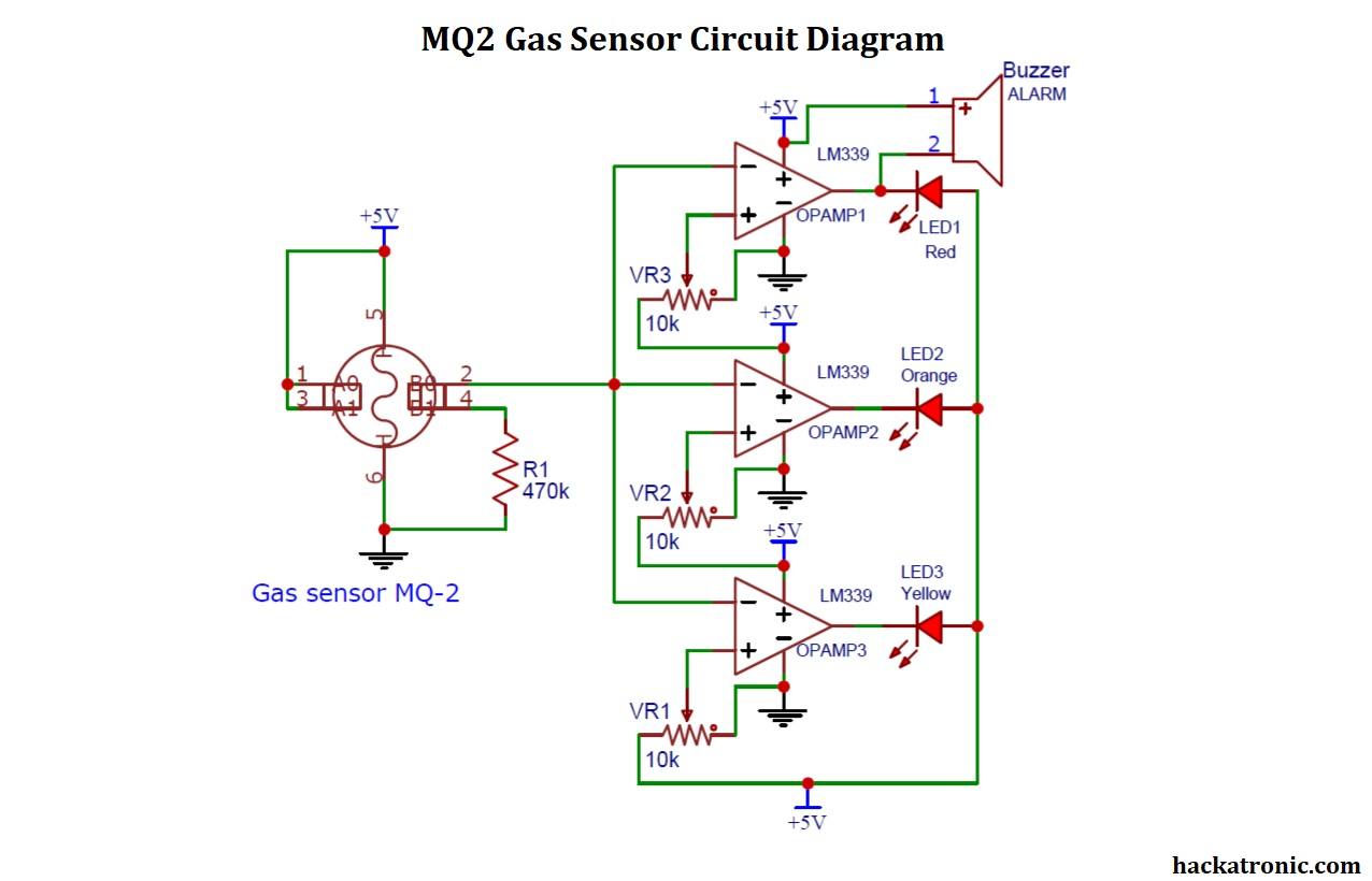
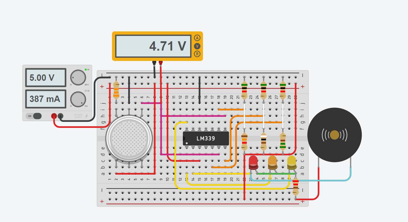
MQ2 Gas Sensor Circuit Diagram:
Components:
- MQ2 Gas sensor
- Lm339 quad opamp lC
- 10k ohm trimmer (potentiometer) 3
- 220-ohm resistor 3
- Buzzer
- 470k ohm resistor
- 5-volt power supply
- Three LED lights Red, Orange, and yellow
- Wires
Gas sensor circuit:
Explanation of MQ2 Gas Sensor circuit:
A Gas sensor circuit is as shown, it contains an MQ2 Gas sensor, LM339 opamp IC, LED lights, and a Buzzer.
Out of 6 terminals, 3 terminals of the gas sensors are connected to +Vcc which are at one side. On the other side, one terminal is pulled to the ground via a 470k ohm resistor, and the middle pin is connected to the ground. The remaining pin is the output pin of the sensor.
The output of the MQ2 sensor is given to the inverting terminal of the three OPAMPs in the quad opamp lC.
3rd pin of the IC is connected to the +Vcc and 12 is the ground terminal.
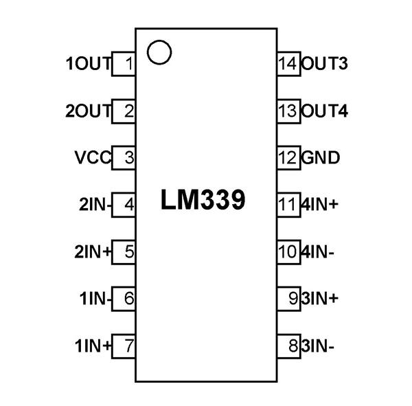
Pinout of LM339 IC:
Pinout of LM339 ic is as shown in the figure
A voltage divider circuit is used to set a reference voltage at the non-inverting terminal of the opamp.
We are using three voltage divider circuits, you can use three trimmers to set the reference voltage at the non-inverting terminal of the opamp.
The output of the three OPAMPs is given to the three LEDs having Red Orange and yellow colors. The color of the LED will indicate the danger level of gas.
Also, a Buzzer is connected to the output of the opamp which will start ringing when the output of the sensor crosses a threshold value set by the trimmer.
You can use this 5-volt power supply to power this circuit or use a battery pack.
Working of the Gas sensor circuit:
This Gas detector circuit works on the open-loop configuration of the opamp.
To know how an opamp works in open-loop read working of the opamp as comparator.
As already said that the trimmers are used to set a reference voltage. In this circuit, the three opamps in lm339 ic are set at 4V, 4.25V, and 4.5V respectively. Use trimmers to set the required threshold voltage.
In the absence of any Gas (LPG, butane, methane) or smoke the output of the MQ2 Gas sensor will be below 4V.
With the presence of LPG or any other petroleum gas, the output of the sensor will start rising and it will cross the threshold voltages. Due to this, the LEDs will eventually glow and buzzer will start, indicating that Gas has been leaked in the surroundings.
Working of MQ2 Gas sensor:
Inside the MQ2 sensor, there is an aluminum oxide Al2O3 based ceramic having a coating of tin oxide SnO2. A heating coil of nickel-chromium is used to heat the sensor. Platinum wires are connected to the tin oxide layer which forms the sensing layer.
The tin oxide layer gets charged when the sensor is heated by the coil. This charged layer attracts oxygen from the atmosphere to its surface. The oxygen molecules get attached to the surface of the sensor. This stops current flow through the sensor.
But when there are gases like LPG, butane, or carbon monoxide, they reduces the tin oxide layer and cause current flow through the device. This is how the MQ2 Gas sensor works.
Applications of gas detector circuit:
This circuit is quite useful for the detection of poisonous gases.
The fixed version of the gas detector is used to measure the presence of various gases in the environment. While the portable version can be used to measure air quality.
Gas sensors are used at petrol pumps and in petroleum product storing places.

I am looking for a source and specifications for the sensor MQ2 not the board with sensor. I need to find out if this is a recognized RoHS, UL etc.. item. Any help is appreciated