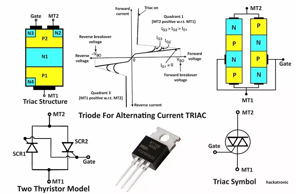
The full form of TRIAC is Triode for Alternating Current. Let’s discuss working of Triac with vi characteristics and Applications. A Triac is a bidirectional device it allows current to flow in both the directions. It is also known as a bidirectional triode thyristor or bilateral triode thyristor. In the SCR family, after the SCR, Triac is the most widely used device for power control.
Triac is a three-terminal electronic device with the terminals named as main terminals 1, 2 (MT1 and MT2) and gate, out of which gate is the control terminal. It is capable of conducting current in both directions when activated.
It is used for switching and phase control applications because it can conduct current in both directions when triggered. Triac is a versatile component present in devices like light dimmers, motor speed controls, and other AC power control systems.
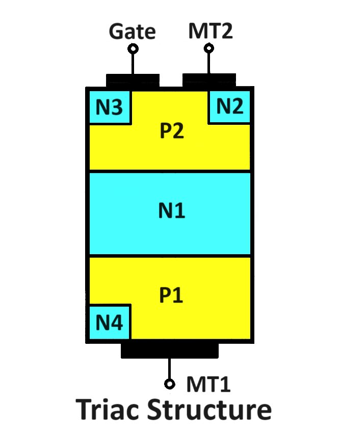
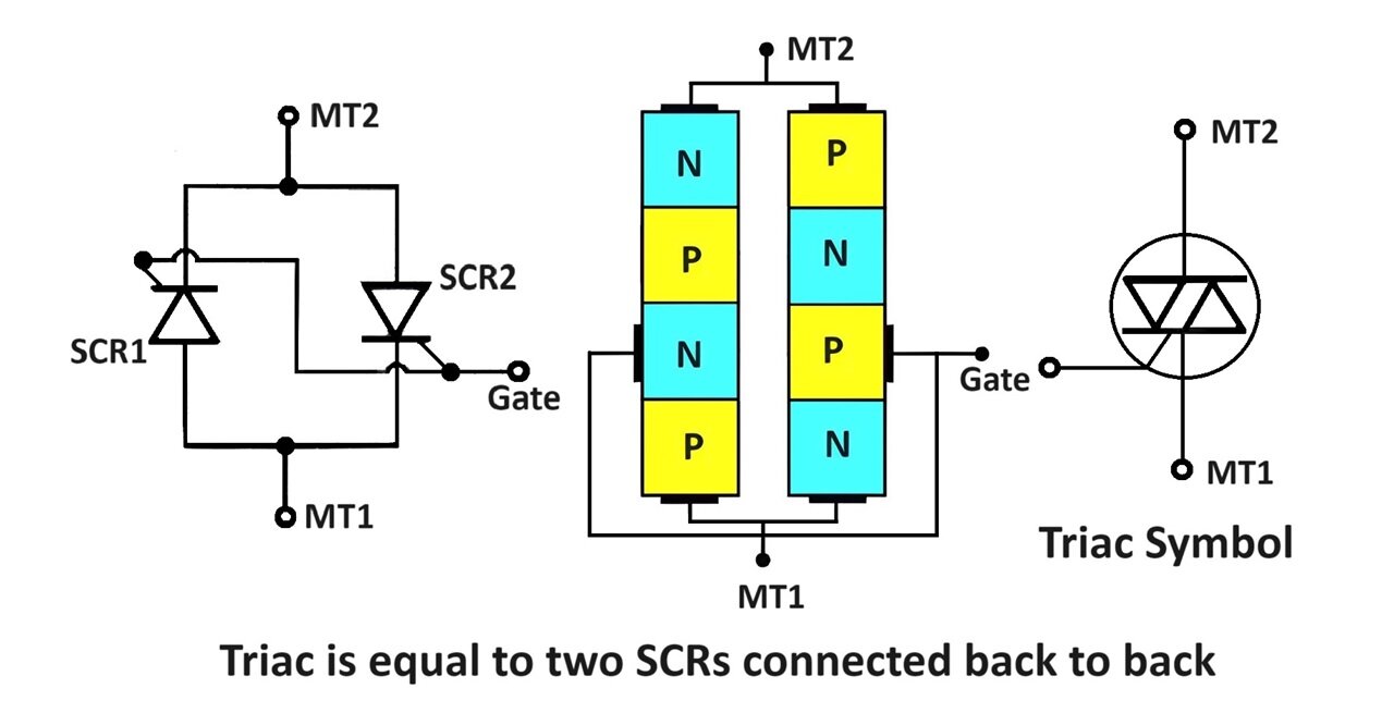
Triacs with large voltage and current ratings are now available in the market. Triac is a bidirectional device, i.e. the current can flow in both the directions through it. (Note that SCR is a unidirectional device). The basic structure of the triac is as shown in Figure.
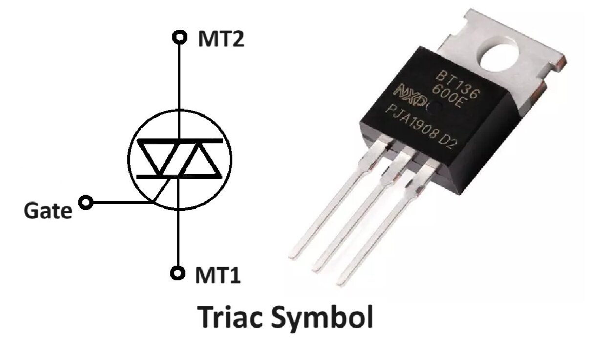
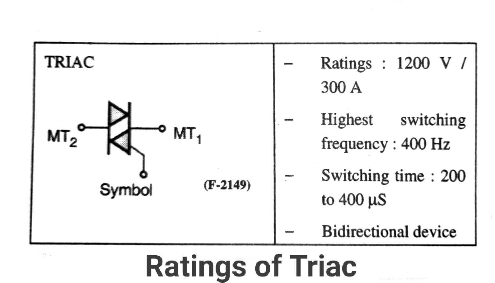
Symbol of TRIAC:
Structure and Terminals
- Main Terminal 1 (MT1)
- Main Terminal 2 (MT2)
- Gate (G)
The main terminals (MT1 and MT2) connect to the AC load, while the gate (G) is used to trigger the device. Its operation is equivalent to two SCRs connected in antiparallel. The two main terminals are designated MT1 and MT2 (main terminal 2 and main terminal 1). The gate is near MT1.
When the gate is open, the Triac will block both the polarities of the voltage across MT1 and MT2 if the magnitude of voltage is less than the breakover voltage of the device. (See the characteristics of the Triac). That means the Triac will remain in the OFF state.
Construction of TRIAC:
VI Characteristics TRIAC:
The characteristics of the Triac are as shown in Figure, and they are similar to those of an SCR both in blocking and conducting states. The only difference is that the SCR conducts only in the forward direction (anode-cathode) whereas the Triac conducts in both the directions.
The other difference in the operation is the triggering mechanism. The Triac can be turned on by applying either a positive or negative voltage to the gate with respect to terminal MT. Whereas the SCR can be triggered only by a positive gate signal.
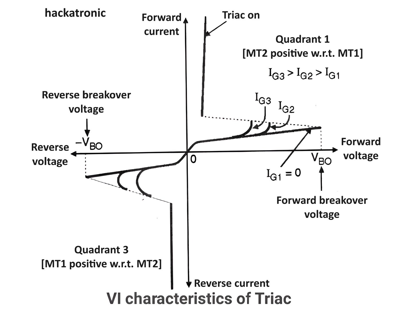
As seen from the Figure, the characteristics of the Triac are the same as that of two back-to-back connected SCRs.
The effect of gate current is also the same i.e. with an increase in the gate current the breakdown voltage decreases. In Triac the gate current can be positive or negative whereas in SCR the gate current can be only positive.
The Triac characteristics and working can be divided into three regions of operation:
- Blocking state or off state.
- Transition or unstable state.
- Conduction state or on the state.
Depending on the polarity of the voltage applied between its MT2 and MT1 terminals, it will operate in either the first quadrant or the third quadrant as shown in Figure.
MT2 positive w.r.t. MT1: Operation is in the first quadrant.
MT2 negative w.r.t. MT1: Operation is in the third quadrant.
The different States of Triac working (operation):
The three important states of Triac operation are:
- Forward blocking state.
- Reverse blocking state.
- Conduction or on state.
Forward blocking state: (MT2 positive with respect to MT1):
When a forward voltage less than the breakover voltage Vn is applied with the gate terminal open the Triac can successfully block the forward voltage without getting turned on.
Reverse blocking state: (MT1 positive with respect to MT2):
When the reverse voltage is less than the breakover voltage Vpo with the gate open-circuited, the Triac will block the reverse voltage without getting turned on.
Conduction or ON state:
The Triac is equivalent to two SCRs connected back-to-back. Therefore, it is a bidirectional device that can conduct in positive as well as negative half cycles of the supply voltage.
The gate current can be positive or negative. The forward and reverse breakover voltage reduces with an increase in the gate current.
Depending on the polarity of supply voltage and the polarity of the gate current the Triac can operate in four different modes of operation as follows: l, ll. lll and Vl.
Triac working & Modes of Operation:
l, ll, III and VI are the four modes of operation of a TRIAC. Here I or IIl represents the quadrant of operation and (+) and (-) signs indicate the direction of gate current. The sensitivity of a mode is defined as the minimum gate current required to tur on a TRIAC in that mode. The sensitivity of I mode is the highest while that of III mode is the lowest.
Triggering Quadrants:
A TRIAC can be triggered in four different modes (quadrants), depending on the polarities of the MT2 and gate currents:
I Quadrant: Positive MT2 voltage with positive gate current.
II Quadrant: Positive MT2 voltage with negative gate current.
III Quadrant: Negative MT2 voltage with negative gate current.
IV Quadrant: Negative MT2 voltage with positive gate current.
Understanding the Working of a TRIAC:
It operates similarly to two thyristors (SCRs) connected in inverse parallel, allowing it to conduct current in both directions. Here’s a detailed explanation of working TRIAC,
Off-State (Blocking State):
When no gate current is applied, the TRIAC remains in the off state, blocking current flow between MT1 and MT2 in both directions. This is similar to an open switch.
On-State (Conducting State):
When a small gate current is applied to the gate terminal, the TRIAC is triggered and begins to conduct current between MT1 and MT2.
The gate current can be positive or negative, allowing the TRIAC to be triggered in both the positive and negative halves of the AC cycle.
Once triggered, the TRIAC remains conducting until the current between MT1 and MT2 drops below a certain threshold (called the holding current), typically at the end of the AC cycle.
Difference between SCR (Thyristor) and TRIAC:
| Feature | SCR (Thyristor) | TRIAC |
|---|---|---|
| Full Form | Silicon Controlled Rectifier | Triode for Alternating Current |
| Number of Terminals | Three (Anode, Cathode, Gate) | Three (MT1, MT2, Gate) |
| Conduction Direction | Unidirectional (conducts current in one direction) | Bidirectional (conducts current in both directions) |
| Gate Triggering | Requires positive gate current only | Can be triggered by positive or negative gate current |
| Control Quadrants | Typically operates in one quadrant | Operates in four quadrants |
| AC/DC Applications | Primarily used in DC and half-wave AC applications | Used in full-wave AC applications |
| Common Applications | Power control, rectifiers, DC motor control | Light dimming, AC motor control, heating control |
| Complexity of Circuit Design | Simpler, usually requires fewer components | More complex, may require additional components for stability |
| Voltage Drop | Typically has a lower voltage drop | Usually has a higher voltage drop compared to an SCR |
| Switching Speed | Faster switching speeds | Slightly slower switching speeds compared to SCR |
Rating of a TRIAC:
Advantages of TRIAC:
- It is a bi-directional device. So, we can control the power delivered to load in both the half cycles of ac supply.
- It is equivalent to two SCRs connected back to back.
- We can turn it on by using a positive as well as negative gate current.
- It is more suitable for resistive loads.
- Triac is more economical than SCRs since inside the same package we get two SCRs connected back-to-back.
- It can control the power delivered to ac loads such as a fan motor.
- It is not necessary to use a protection diode across the Triac.
- We can use a single heat sink.
- Fewer components are needed for AC power control compared to other methods.
Disadvantages of TRIAC:
- We cannot use it as a controlled rectifier.
- Low dv/dt rating than SCR. So the possibility of an accidental turn on is higher than that of SCR.
- Low di/dt rating.
- Suitable for resistive loads only. Not suitable for controlling power to highly inductive loads.
- Its power rating is lower than that of SCR. Triggering circuits need to be designed more carefully.
Applications of TRIAC:
TRIACs (Triode for Alternating Current) find extensive applications across various industries due to their ability to control power in AC circuits. Here are some common applications:
Solid-State Relays:
As a static switch providing electronic switching without mechanical parts, increasing reliability and lifespan.
Light Dimming:
TRIACs are widely used in Flasher circuit and dimmer switches. It is used to control the brightness of incandescent, halogen, and dimmable LED lights. By adjusting the conduction angle of the TRIAC, users can regulate the amount of power delivered to the light source, thus altering its brightness.
Motor Speed Control:
TRIACs are employed in motor speed controllers for AC motors used in appliances like fans, mixers, drills, and power tools. By varying the voltage and frequency applied to the motor, TRIACs regulate its speed and torque output.
Heating Control:
TRIACs are used in electric heating systems to control the power delivered to resistive heating elements. Applications include electric stoves, ovens, water heaters, and industrial furnaces, where precise temperature control is required.
Power Supplies:
TRIACs are utilized in AC power supplies to regulate the output voltage by controlling the amount of power delivered to the load. This is commonly seen in variable power supplies used in laboratories and electronics testing.
AC Switching:
TRIACs serve as solid-state switches in AC circuits, replacing traditional mechanical relays. They offer faster switching speeds, higher reliability, and noiseless operation, making them ideal for applications like home automation, HVAC systems, and industrial control systems.
Fan Speed Regular & Control:
TRIAC-based circuits control the speed of AC fans and blowers in HVAC systems, air purifiers temperature control, and cooling units. By adjusting the phase angle of the AC waveform, TRIACs regulate the fan speed to maintain desired airflow and temperature levels.
Motorized Appliances:
TRIACs are used in various motorized appliances such as food processors, blenders, juicers, and sewing machines to control the motor speed or adjust operational modes.
Security Systems:
TRIACs play a role in security systems for controlling AC-powered devices like sirens, alarms, Proximity detector, and door locks. They enable remote activation and deactivation of these devices, enhancing security and convenience.
Lighting Controls:
TRIAC-based lighting control systems are used in commercial buildings, theaters, and stadiums for dynamic lighting effects, scene setting, and energy management. They offer precise control over multiple lighting zones and fixtures.
Medical Equipment:
TRIACs are integrated into medical devices such as surgical equipment, patient monitors, and diagnostic instruments for regulating power delivery to various components and subsystems.
Understanding the working of a TRIAC is essential for designing efficient power control systems in a wide range of electronic applications. Its unique ability to control AC power bidirectionally with a single component makes it a fundamental building block in modern electronics.
What is Thyristor? Working, Symbol, Construction, Types, Operation, Protection and Applications
IGBT-Insulated Gate Bipolar Transistor its Working and Applications
