An Insulated Gate Bipolar Transistor in short IGBT is a three-terminal semiconductor device it is a hybrid of MOSFET and BJT for high efficiency and fast switching. The power BJT has the advantage of low on state power dissipation, but it cannot be switched at faster rates due to longer turn-off time, whereas MOSFETs have a very high switching speed but their power handling capacity is not as good as that of BJTs.
The power MOSFET can be switched at much higher frequency but has a drawback of higher on state power loss.
Therefore, we made an insulated gate bipolar transistor (IGBT) to combine BJTs and MOSFETS monolithically on the same silicon wafer to develop a new device that will have the best qualities of both, BJT and MOSFET.
Other names for this device are GEMFET, COMFET (conductivity modulated field-effect transistor), IGT (insulated gate transistor), and bipolar mode MOSFET or bipolar MOS transistor.
Features of IGBT:
The important features of IGBT are as follows:
Low on-state voltage drop
Low on-state power loss
It has a higher switching frequency than that of a power BJT.
IGT has the best qualities of BJT and MOSFET.
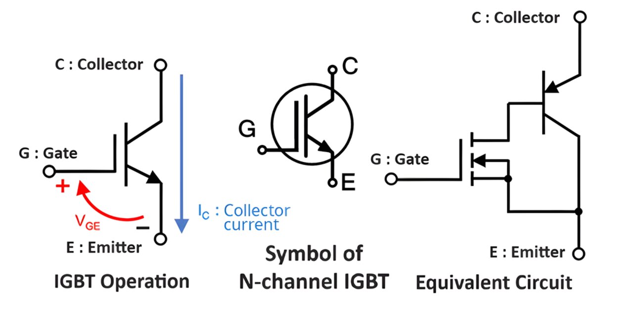
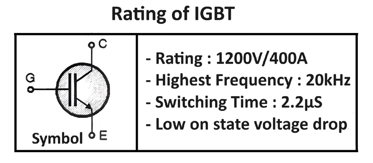
The circuit symbol:
The circuit symbols for an n channel IGBT are as shown in Figure. It is a three-terminal device, gate being the control terminals.
The directions of the arrowheads will reverse in a p channel IGBT.
The symbol shown in Figure is almost identical to that used for the n channel power MOSFET, but with the addition of an arrowhead in the drain terminal pointing into the device.
The symbol shows that the insulated-gate bipolar transistor is considered to be a BJT with MOSFET gate input.
This device has a collector and emitter instead of a drain and source. The controlling terminal however is the gate terminal(G).
This symbol indicates that it has output characteristics similar to power BJT and input characteristics similar to the power MOSFET.
IGBT Pinout:
An IGBT consists of four layers of semiconductor materials forming an N-P-N-P structure:
- Emitter (E): This is the source terminal.
- Collector (C): This is the drain terminal.
- Gate (G): This is the control terminal, similar to a MOSFET gate.
- Substrate/Body: The bulk of the semiconductor material.
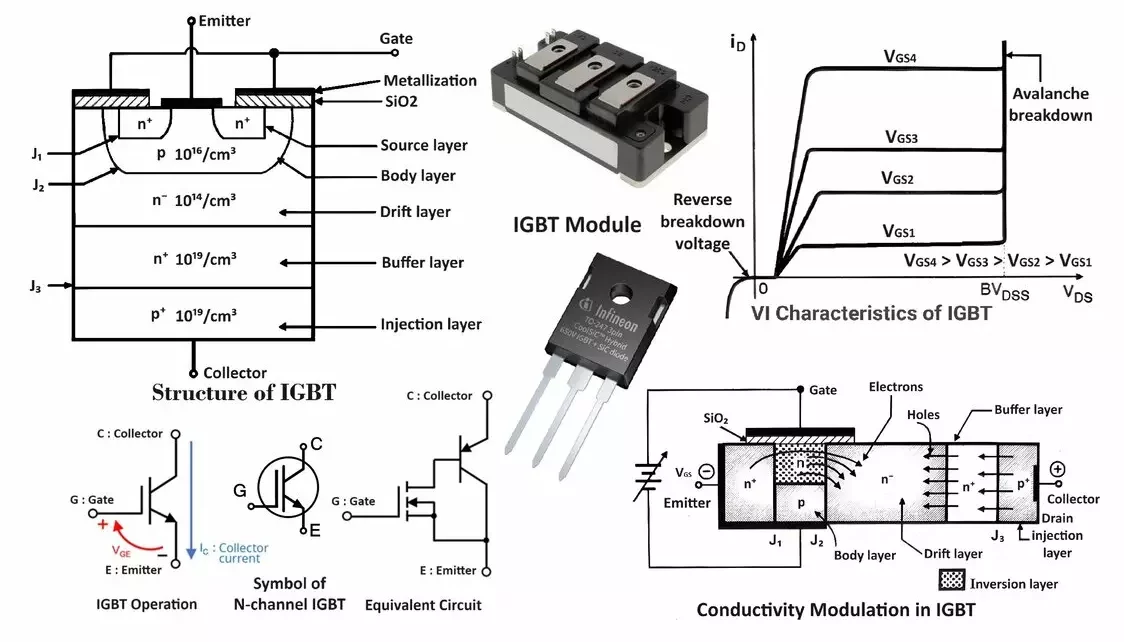
Read this article to understand the VI characteristics of IGBT.
Construction of IGBT – Basic Structure:
The vertically oriented structure of IGBT is as shown in Figure.
Like all other devices, IGBT also uses the vertically oriented structure to maximize the area available for the current flow.
This will reduce the resistance offered to the current flow and hence the on-state power loss taking place in the device.
The IGBT also uses a highly interdigitated gate-source structure to reduce the possibility of source/emitter current crowding.
The doping levels used in different layers of IGBT are similar to those used in the comparable layers of the power MOSFET structures except for the body region. The main difference in the structure of IGBT as compared to that of a MOSFET is the existence of a p+ (injection layer or drain layer) layer that form’s the drain of the IGBT.
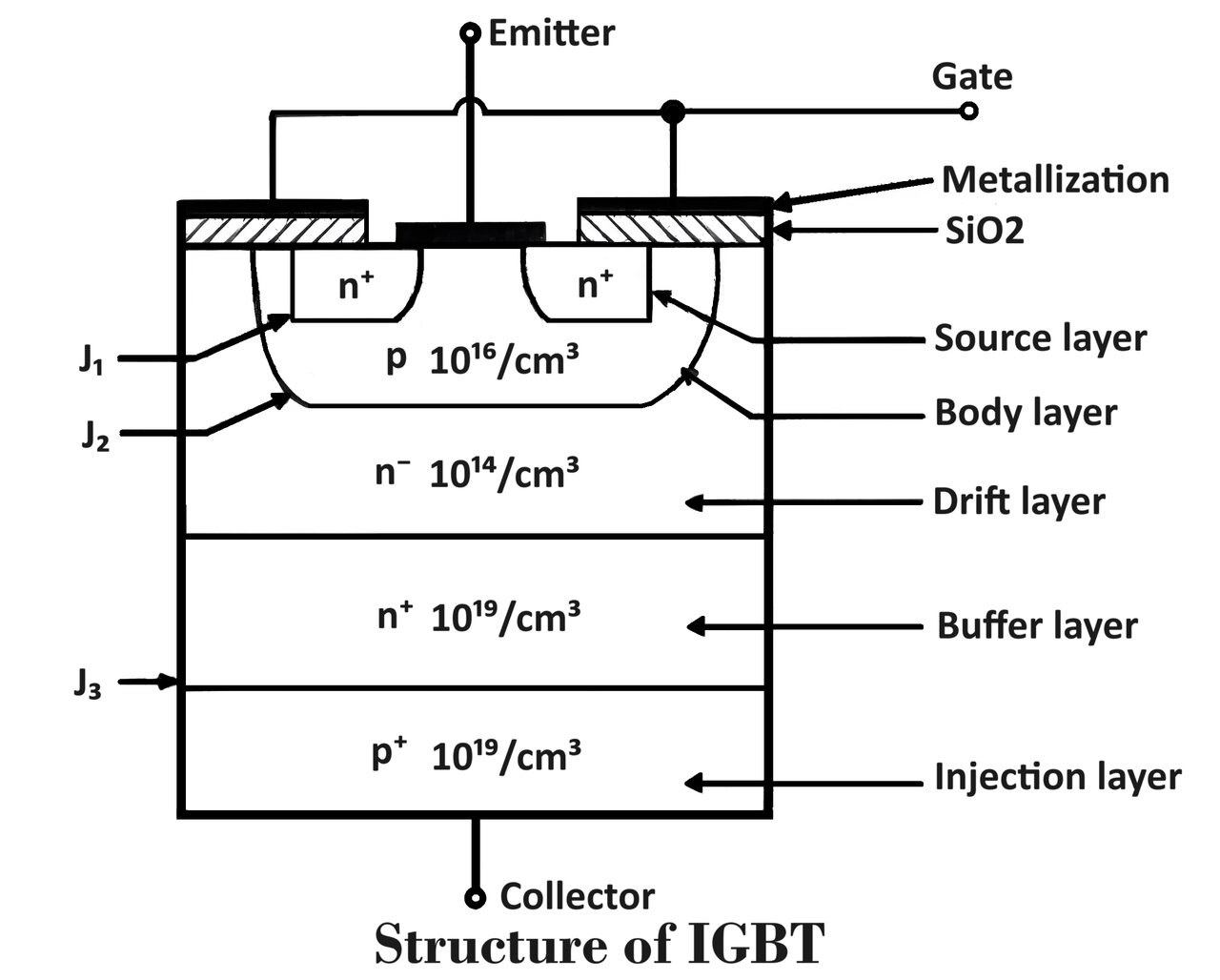
This device also uses the n-type drain drift layer which improves its breakdown voltage capacity. This is the same as that in case of power MOSFETs.
It is also possible to make a p-channel IGBT by changing the doping type in each of the layers of the device.
n+ Buffer Layer:
The n+ buffer layer is not a must (it is an optional layer) for the operation and some IGBTs do not have it. IGBTs without a buffer layer are known as symmetric IGBTs whereas those with the buffer layer are called asymmetric IGBTs.
The n+ buffer layer improves the operation of IGBT in two important aspects:
It reduces the on-state voltage drop across the device.
It shortens the turn-off time.
But the drawback is that the buffer layer reduces the reverse blocking capacity of the device to a great extent.
Operation / Working of Insulated Gate Bipolar Transistor:
The working of an IGBT can be divided into two main modes: off-state and on-state.
Off-State
When the gate-emitter voltage () is below a certain threshold (typically 4-6V), the IGBT is in the off-state, meaning no current flows from the collector to the emitter. This is because the MOSFET part of the IGBT does not create an inversion layer in the P-region, and thus the device behaves like an open switch.
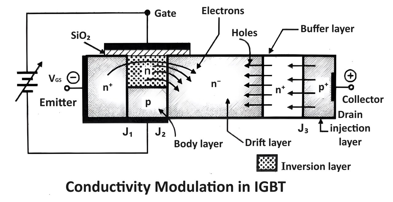
On-State
When exceeds the threshold voltage, the IGBT turns on. Here’s what happens step by step:
- Gate Voltage Applied: A positive voltage applied to the gate relative to the emitter creates an electric field, turning on the MOSFET part of the IGBT.
- Inversion Layer Formation: This field induces an inversion layer in the P-region adjacent to the N-region, allowing electrons to flow from the emitter to the collector.
- Carrier Injection: The N-channel formed allows electrons to flow from the emitter into the N-region of the structure. This flow of electrons injects holes from the P-region into the N-region, creating a low-resistance path for current flow between the collector and emitter.
Types of Insulated Gate Bipolar Transistors:
IGBTs come in two main types based on their structural design: Non-Punch Through (NPT) IGBTs and Punch Through (PT) IGBTs. These types differ primarily in their construction and performance characteristics. Here’s a comparison and description of each:
| Feature | Non-Punch Through IGBT | Punch Through IGBT |
|---|---|---|
| Structure | No N+ buffer layer | Includes N+ buffer layer |
| Voltage Blocking | Symmetrical | Asymmetrical |
| Switching Speed | Slower | Faster |
| Tail Current | Longer | Shorter |
| Switching Losses | Higher | Lower |
| Ruggedness | Higher | Lower |
| On-State Voltage Drop | Higher | Lower |
| Thermal Management | Better | Requires careful management |
| Applications | Industrial motor drives, power supplies | Renewable energy systems, EV drives, UPS |
The choice between NPT and PT IGBT depends on the specific application requirements:
- NPT IGBT: Preferred for applications requiring higher robustness and symmetrical voltage blocking capability. Found in industrial motor drives and other rugged applications where switching speed is less critical.
- PT IGBT: Suitable for applications where high switching speed and efficiency are crucial. Applicable in inverters for solar and wind energy systems, electric vehicle drives, and high-efficiency power supplies.
Understanding these differences helps in selecting the appropriate IGBT type for specific power electronics applications, balancing performance, efficiency, and reliability.
Ratings of IGBT:
Here are the ratings of IGBT
Advantages of IGBT over BJT:
It is a voltage-controlled device so that gate driving is easy.
It can switch at a higher frequency than BJT. Typically =20kHz.
They can be easily connected in parallel. The second breakdown does not take place.
No need snubber circuits for their protection.
Advantages of IGBT over MOSFET:
On state voltage drop across IGBT is less than that across MOSFET.
Low on-state power dissipation.
IGBTs can handle larger power than MOSFETs.
Advantages of Insulated Gate Bipolar Transistor (IGBT):
- High Efficiency: IGBTs have a low on-state voltage drop, which results in lower conduction losses and higher efficiency, especially in high-power applications.
- High Current Capability: IGBTs can handle high currents, making them suitable for high-power applications such as industrial motor drives, electric vehicles, and power inverters.
- Voltage Control: The gate of an IGBT is voltage-controlled, similar to a MOSFET, which simplifies the drive circuitry. This means that only a small current is needed to maintain the gate voltage, reducing the power required to control the device.
- High Input Impedance: The high input impedance of the IGBT gate means it draws very little current, making it easier to interface with digital circuits and microcontrollers.
- Ruggedness: IGBTs are robust devices capable of withstanding significant electrical and thermal stresses, making them reliable in harsh environments.
- Reduced Size and Weight: Compared to BJTs, IGBTs can deliver higher power densities, which means smaller and lighter designs for power electronic systems.
Disadvantages of Insulated Gate Bipolar Transistor IGBT:
- Switching Speed: IGBTs generally have slower switching speeds compared to MOSFETs. This is due to the presence of minority carriers in the device, which can cause a tail current during turn-off, leading to higher switching losses.
- Thermal Runaway: IGBTs can be susceptible to thermal runaway if not properly managed. This is because the on-state voltage drop decreases with increasing temperature, potentially leading to increased current and further heating.
- Complex Drive Requirements: Although the gate drive requirements are less complex than those of BJTs, IGBTs still require careful gate drive design to ensure fast switching and to manage the tail current.
- Higher Cost: IGBTs can be more expensive than MOSFETs, particularly for high-voltage and high-current applications. The manufacturing process is more complex, which can add to the cost.
- Turn-off Losses: The tail current during turn-off leads to higher energy dissipation during switching, which can be a disadvantage in high-frequency applications where switching losses are critical.
- Temperature Sensitivity: While IGBTs are robust, their performance can be sensitive to temperature changes, necessitating efficient cooling and thermal management strategies.
Applications of IGBT:
Insulated Gate Bipolar Transistors (IGBTs) are widely used in various applications due to their high efficiency, high current-handling capability, and ease of control. Here are some of the primary applications of insulated-gate bipolar transistor (IGBTs):
1. Motor Drives
IGBTs are extensively used in motor drive applications for industrial and commercial purposes. They provide efficient control and conversion of electrical power to drive motors in:
- Industrial motors: Used in manufacturing and processing plants.
- Electric vehicles (EVs): Used in the traction inverters to control the electric motors.
- HVAC systems: For controlling the compressors and fans in heating, ventilation, and air conditioning systems.
2. Power Inverters
IGBTs are key components in power inverter circuits that convert DC to AC power. They are used in:
- Solar inverters: Converting the DC power generated by solar panels to AC power for grid or home use.
- Uninterruptible Power Supplies (UPS): Ensuring a continuous power supply by converting stored DC power from batteries to AC power during power outages.
- Wind turbines: For converting variable AC power generated by wind turbines to stable AC power suitable for grid use.
3. Electric and Hybrid Vehicles
In electric and hybrid vehicles, IGBTs are used in power control units (PCUs) for:
- Traction inverters: Converting DC power from the battery to AC power to drive the electric motor.
- DC-DC converters: For voltage conversion and regulation within the vehicle’s electrical system.
- Battery management systems: Ensuring efficient and safe charging and discharging of the vehicle’s battery.
4. Renewable Energy Systems
IGBTs are essential in renewable energy systems, providing efficient power conversion and control:
- Photovoltaic (PV) systems: Used in the inverters that convert DC power from solar panels to AC power.
- Wind energy systems: Used in converters and inverters to manage power generated from wind turbines.
5. Industrial Applications
In industrial applications, IGBTs are used for efficient power control and energy management:
- Induction heating: Used in induction heating systems for melting, welding, and other heating processes.
- Welding machines: For precise control of the welding current.
- Power supplies: In switch-mode power supplies (SMPS) and other industrial power supply units.
6. Consumer Electronics
IGBTs are used in consumer electronics for power management and control:
- Home appliances: Such as washing machines, refrigerators, and air conditioners, where they are used for motor control and power conversion.
- Audio amplifiers: In high-power audio amplification systems for efficient signal amplification.
7. High Voltage Direct Current (HVDC) Systems
IGBTs play a crucial role in HVDC transmission systems:
- Converters: Used in HVDC converters to efficiently convert AC to DC for long-distance transmission and then back to AC at the receiving end.
- Power control: For managing the flow of electricity in HVDC grids, ensuring stable and efficient power transmission.
8. Medical Equipment
In the medical field, IGBTs are used in various high-reliability applications:
- MRI machines: For controlling the power to the MRI coils.
- X-ray machines: In the high-voltage power supplies for generating X-rays.
- Ultrasound equipment: For managing the power delivery to ultrasound transducers.
In summary, IGBTs are versatile and efficient devices used across a wide range of applications. They are found in Switching mode power supplies (SMPS), UPS systems (inverters), AC motor controllers, Choppers, industrial motor drives and renewable energy systems to electric vehicles and consumer electronics. Their ability to handle high power levels with efficient switching makes them essential in modern power electronics.

Thanks for your information..
I have welding machine with rectifier, IGBT module 100A 600V and 2 big non polar capacitors. Some one disconnected the capacitors from IGBT terminals. Now I want to fix them to their original position. Would you mind to assist me?
I am very much impressed with your knowledge of IGBT. Thank you so much.
Please refer the circuit diagram of you welding machine