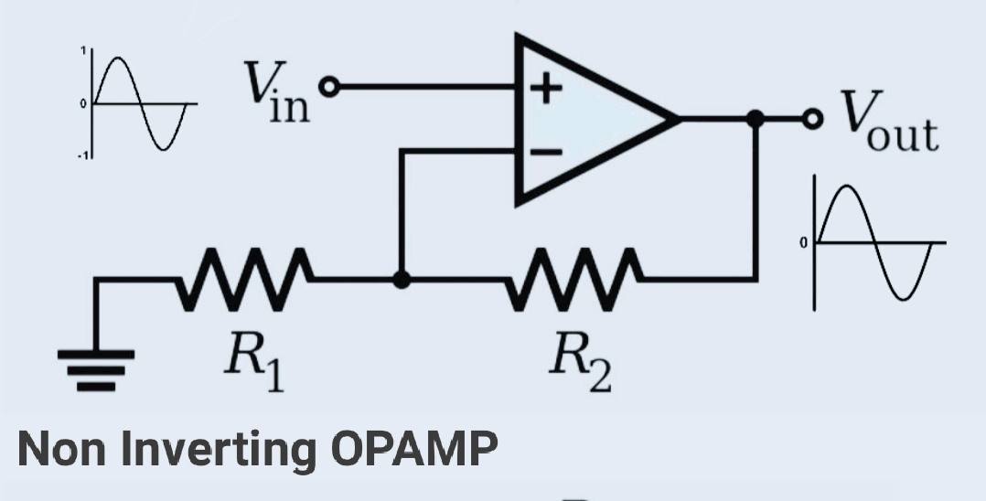
A non-inverting amplifier is an OPAMP circuit configuration whose output is in phase with the input signal at the non-inverting input. The input signal is applied at the non-inverting input of the opamp. A non-inverting amplifier also acts as a voltage follower circuit.
The non-inverting amplifiers also have negative feedback which is used to control the gain of the amplifier. Feedback contains a voltage divider circuit that provides a part of the output to the input terminal. This OPAMP has a high input impedance and a low output impedance. This makes it an ideal buffer.
Non-Inverting Amplifier circuit:
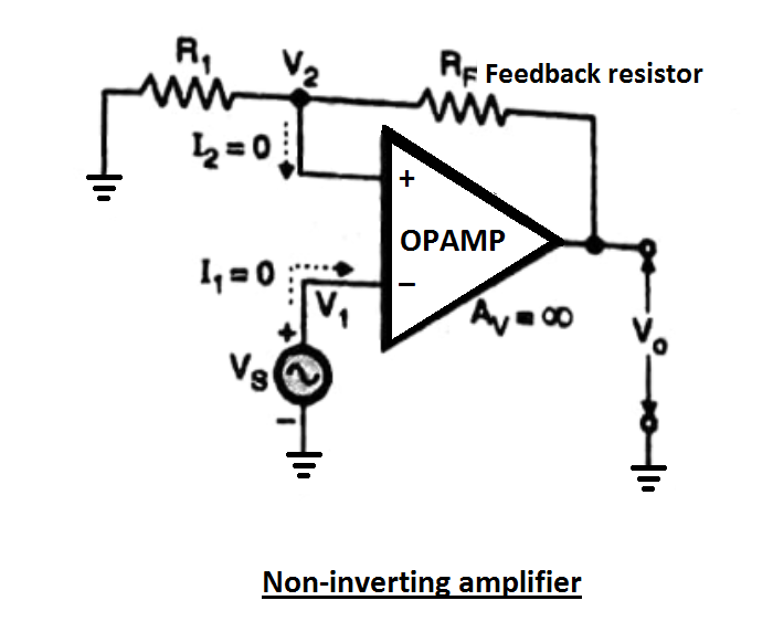
The non-inverting amplifier is as shown
- The signal which is to be amplified is applied to the non-inverting +ve input terminal and the inverting input terminal is connected to ground wire resistor R1.
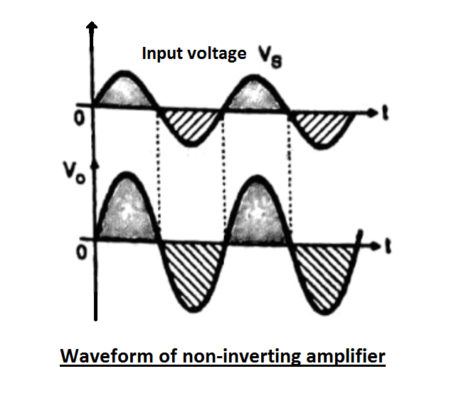
- The input and output voltages are in phase with each other, their phase difference is 0 or 360 degrees.
- The feedback resistor Rf introduces negative feedback at the negative inverting input terminal of the opamp. It makes a voltage divider with a ground resistor.
Expression for closed-loop voltage gain:
To derive expression, we are using an ideal opamp. Input resistor Ri = ♾️, current internet input terminals will have 0 value, (I1 = I2 = 0).
The voltage across R1 is given by
V2 = R1 ÷ [(Rf + R1)] × Vo
As per the concept of virtual short discussed earlier,
V1 = Vs = V2
Substituting the value of b2 in the above expression we get,
Vs = R1(Rf + R1)] ×Vo
Close loop voltage gain,
Avf = Vo/Vs = (R1 + Rf) ÷ R1
Avf = 1 + (Rf÷R1)
Vo = Avf × Vs
Conclusion from the above expression for Avf:
- The positive sign of the equation indicates that the input and output are in phase with each other.
- The closed-loop voltage gain is always greater than unity 1.
- The value of Avf is adjustable it can be adjusted by varying the value of Rf and R1. Generally, a variable resistor is present in place of Arif to adjust the closed-loop gain to its desired value.
- Avf is independent of the open loop gain of the opamp. It depends only on the value of RF and R1.
Difference between Inverting amplifier & Non-inverting amplifier:
| Sr, No. | parameters | Inverting Amplifier | Non-inverting Amplifier |
|---|---|---|---|
| 1 | Voltage gain | Avf = – Rf/R1 | Avf = 1 + Rf/R1 |
| 2 | Phase difference between input and output Voltages | 180° out of phase | In phase |
| 3 | Value of Voltage gain | Can be greater than, less than or equal to unity | Always greater than or equal to unity |
| 4 | Input resistance | Equal to R1 | Very large |
Concept of virtual short:
In a non-inverting amplifier, there is a virtual shot between two input terminals.
It means that there is a short circuit for voltage but an open circuit for current. It is due to the two reasons,
- The value of Rin is infinite there for current at both the input terminals is zero.
- The difference between input voltages (V1 – V2) is zero hence Aol is infinite.
Virtual short is an ideal concept. If we operate the opamp in the linear region, virtual short can give accurate values with -Ve feedback.
As the voltage gain reaches infinity there is a virtual short between the input terminal
Because of virtual short inverting voltage follows non-inverting input voltage. If the input signal at non-inverting terminal changes, then the voltage at inverting terminal also changes by the same amount. This action is called “Bootstrapping“.
OP-AMP tutorial:
-
Opamp as Differentiator (active differentiator)
-
OP AMP integrator
-
Voltage Follower OPAMP or buffer Amplifier
-
Non Inverting Amplifier (OPAMPs)
-
Inverting amplifier (OPAMPs)
-
741 Op Amp, First Operational Amplifier IC
-
What is operational amplifier? basics concepts
-
Automatic Battery Charger circuit using LM358 OP-AMP
