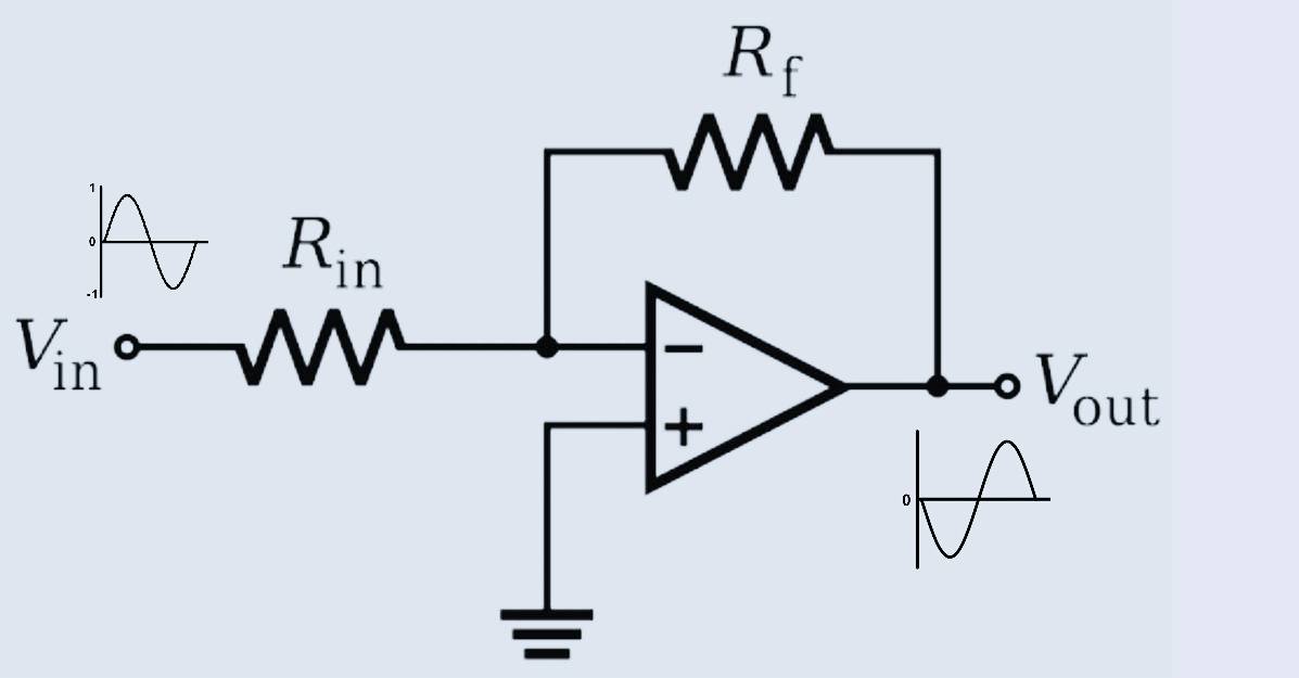
The inverting amplifier is one of the types of closed loop opamp configuration. In this configuration, the non-inverting (+ve) terminal of the opamp is connected to the ground, while the inverting terminal acts as input terminal. Negative feedback is present between the output terminal and (-ve) inverting terminal of OPAMP.
Importance of negative feedback in Inverting amplifier:
The open loop gain of an operational amplifier is very high up to 120 dB. Practically this gain is unstable and difficult to control.
Get SEO Backlinks
If we use the OPAMP in open loop configuration it will be highly sensitive to a small input in (μV) microvolts, and the output will swing between +Ve high and -Ve low.
In order to control the gain of the amplifier, we introduce negative feedback. As the gain of an amplifier is very high, we can sacrifice some gain for stability. Negative feedback is the most common way to stabilize amplifier gain. In this method by using a resistor Rf some part of the output is feedback to the negative input terminal.
This -Ve feedback produces stability to the output of the amplifier.
Concept of negative feedback:
Negative feedback is the process of feeding back output to the input terminal of the operational amplifier. To make feedback negative it is applied to -ve inverting terminal. Due to this, the differential voltage becomes smaller.
Whenever there is a change in input the output also changes due to this the negative feedback also changes which stabilizes the gain, making a closed loop. That’s why the gain is called closed-loop gain.
The voltage appearing at the inverting terminal is the sum of the input signal and -Ve feedback signal, Making a summing point. Hence, we must separate the input signal from the feedback signal by using a resistor between input and summing point.
The inverting amplifier:
- The signal which is to be amplified is applied at the inverting input terminal of the OP-AMP.
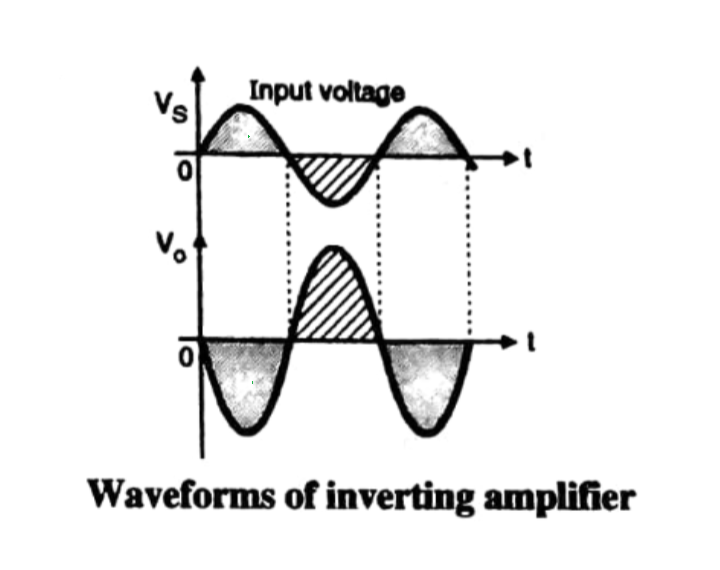
- The amplifier output signal will be 180 degrees out of phase with the input signal. In other words, the output signal is inverted.
- Therefore, the amplifier is known as an inverting amplifier.
Operation of OPAMP circuit:
- The signal which is to be amplified is connected to the inverting terminal via resistor Ri.
- the resistor Rf connected between the output terminal and inverting input terminal is called as feedback resistor. it introduces negative feedback.
- The non-inverting (+) input terminal is connected to ground.
- Open peace and ideal one it’s open low voltage gain AV is -♾️ and input resistance is ♾️. The negative sign indicates an inverting configuration.
- The input and output voltages are out of phase. The output voltage is amplified and inverted version of input signal Vs.
Expression for the closed-loop voltage gain:
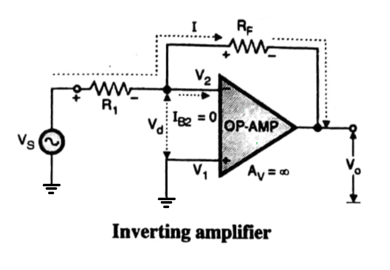
From the circuit, we can say that
Vo = [Av]×Vd
Vd = [Av] ÷ Vo
Where Av = open-loop gain
As we know that open loop gain of OPAMP is ∞,
Vd = Vo ÷ 0 = 0
Vd = V1 - V2
since, Vd = 0
V2 - V2 = 0
As the +ve input terminal is connected to ground, V1 = 0
thus, V2 = 0
- Since the input resistance is ♾️ the current going into the opamp will be zero therefore current I pass through which will also pass through RF as shown.
- As the input voltage is measured with respect to the ground which is V2. we can say that the input voltage vs is the voltage across R1 and voltage across RF if the output voltage.
- The input voltage vs is given by,
Vs = IR1
- And the output voltage is given by,
Vo = -IRf
V2 is approximately at ground potential.
Closed loop gain
Avg = Vo /Vs
Substituting the values of Vs and Vo we get,
Avf = IRf /IR1 = - Rf/R1
Vo = Avf *Vs
The conclusion from the above expression:
- The value of closed-loop voltage gain Avf does not depend on the value of open-loop voltage gain Av.
- the value of closed-loop gain can be adjusted by wearing the value of resistors Rf and R1. Rf is a potentiometer to adjust the gain.
- The output voltage is amplified and inverted version of the input voltage.
-
Opamp as Differentiator (active differentiator)
-
OP AMP integrator
-
Voltage Follower OPAMP or buffer Amplifier
-
Non Inverting Amplifier (OPAMPs)
-
Inverting amplifier (OPAMPs)
-
741 Op Amp, First Operational Amplifier IC
-
What is operational amplifier? basics concepts
-
Automatic Battery Charger circuit using LM358 OP-AMP
