The Controller Area Network in short CAN Bus Communication Protocol has a fascinating history. It was developed by Robert Bosch GmbH in the 1980s to address the need for a robust serial communication protocol for in-vehicle networks. It is widely used communication protocol in automotive and industrial applications.
History of Can bus Protocol:
Here’s a brief history of CAN bus communication protocol:
Development Stage (1980s):
CAN was developed by Bosch in the early 1980s primarily for automotive applications. The main goal was to create a reliable and efficient network for communication among electronic control units (ECUs) in vehicles.
Standardization (1990s):
In the early 1990s, CAN became an international standard, known as ISO 11898. This standardization helped to establish CAN as a widely used protocol not only in automotive applications but also in various industrial automation, medical devices, and other fields.
Expansion and Variants:
Over time, several variants of the CAN protocol emerged to suit different application requirements. One notable variant is the CANopen protocol, which is often used in industrial automation.
In the automotive industry, several higher-layer protocols were developed on top of the CAN physical layer, such as J1939 for heavy-duty vehicles and OBD-II for vehicle diagnostics.
Improvements and Enhancements:
As technology advanced, improvements and enhancements were made to the CAN protocol. For example, CAN FD (Flexible Data-Rate) was introduced to increase the data rate and payload length compared to traditional CAN.
CAN FD allows for faster transmission speeds and larger data frames, making it suitable for more demanding applications.
Adoption in Other Industries:
While initially developed for automotive applications, CAN found its way into various other industries due to its reliability, robustness, and low cost. It is widely used in sectors such as industrial automation, aerospace, maritime, medical devices, and more.
Future Developments:
As technology evolves, so does the CAN protocol. Efforts continue to enhance its performance, reliability, and security to meet the demands of emerging applications. With the rise of electric vehicles, autonomous driving, and connected systems, CAN remains a crucial communication protocol in modern vehicle architectures, alongside newer protocols like Ethernet and FlexRay.
Overall, the history of the CAN bus communication protocol reflects its journey from a specialized automotive communication solution to a widely adopted standard in various industries, with ongoing developments to keep pace with technological advancements.
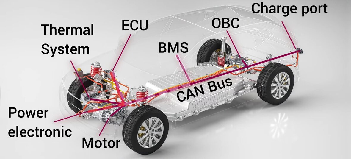
CAN Bus Network
Architecture of CAN bus Communication Protocol:
The Controller Area Network (CAN) bus is a widely used communication protocol in automotive and industrial applications due to its reliability, efficiency, and real-time capabilities. Here’s an overview of the architecture of the CAN bus communication protocol:
Message-based Protocol: CAN is a message-based protocol, meaning devices communicate by sending messages rather than establishing a connection.
Differential Signaling: It uses differential signaling, where the difference in voltage between two wires is used to transmit data. This makes it resistant to noise and interference.
Broadcast Communication: Messages are broadcast to all nodes on the network. Each node then decides whether to accept the message based on the identifier contained within it.
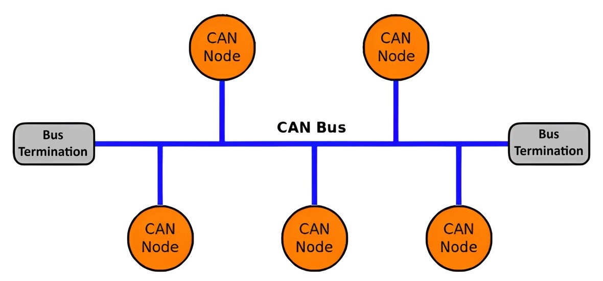
Basic Components:
Nodes: These are the devices connected to the CAN bus. Nodes can be sensors, actuators, controllers, or any other electronic control unit (ECU) in a network.
CAN Bus: The physical medium through which nodes communicate. It typically consists of two wires: CAN High (CANH) and CAN Low (CANL).
Transceivers: Each node is connected to the CAN bus through a transceiver, which converts the digital signals from the node into the differential signals required for transmission over the bus.
Controller: The controller manages the communication process on the CAN bus. It handles message transmission, reception, arbitration, error detection, and error handling.
Communication Process:
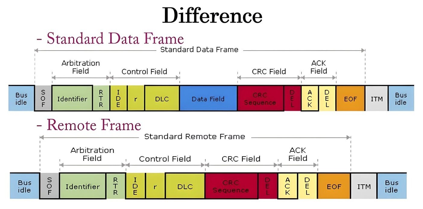
Message Format: CAN bus messages are organized into frames. There are four types of frames:
Data Frame: Carries actual data from the sender to one or multiple receivers.
Remote Frame: Requests specific data from another node.
Error Frame: Indicates an error condition.
Overload Frame: Used to delay transmission when the bus is overloaded.
CAN Standard VS Remote Frame
Message Arbitration: Nodes compete for bus access based on priority (determined by the message ID). Lower ID means higher priority. The node with the highest priority message to transmit gains access to the bus.
Message Transmission: After winning arbitration, the node transmits the message bit by bit. Each node listens to the bus to ensure successful transmission.
Error Detection and Handling: CAN has built-in error detection and handling mechanisms including. It sends an error frame. Nodes receiving an error frame take appropriate action, such as retransmitting the message.
Cyclic Redundancy Check (CRC): Used to detect errors in transmitted messages.
Acknowledgement (ACK): Each message sent is acknowledged by the receiving node. If not acknowledged, the sender retransmits.
Collision Detection and Resolution: Nodes detect collisions during transmission and resolve them via a mechanism called Carrier Sense Multiple Access with Collision Detection (CSMA/CD).
CAN 2.0A (11-bit identifiers) and CAN 2.0B (29-bit identifiers): Differ in the length of identifiers they support.
CAN FD (Flexible Data-rate): Introduces higher data rates and larger data frames compared to classical CAN
Packet/Frame Format of CAN Bus:
Controller Area Network (CAN) is a popular communication protocol used in automotive and industrial applications. The CAN bus packet format consists of several key components:
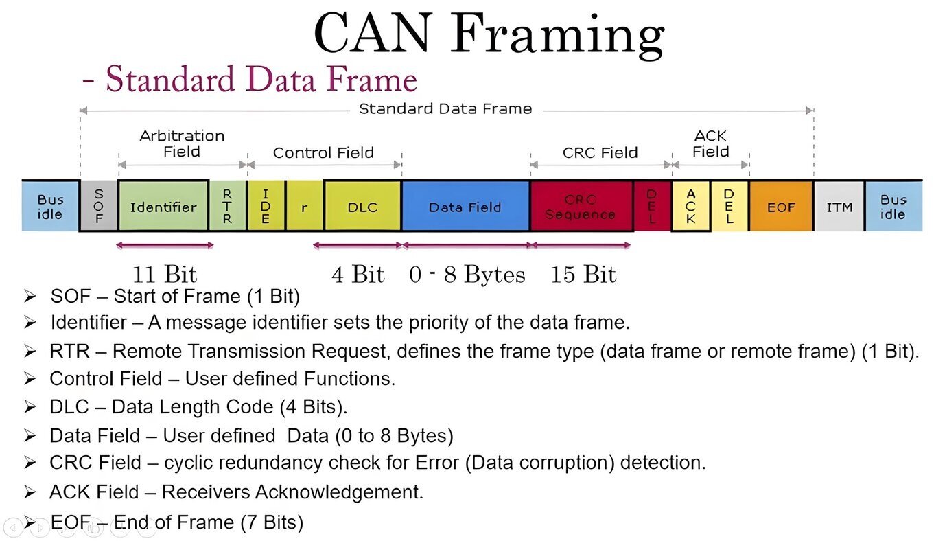
CAN Standard Frame
Start of Frame (SOF): This is a single dominant (logic 0) bit indicating the start of a frame. It synchronizes all nodes on the bus to the beginning of a message.
Arbitration Field: This field contains the identifier of the message and its priority. In a standard CAN frame, the identifier is 11 bits long (Standard Frame Format), while in an extended frame, it is 29 bits long (Extended Frame Format).
Control Field: This field specifies the data length (DLC) and other control bits.
Data Field: This field carries the actual data being transmitted. Its size can vary from 0 to 8 bytes.
CRC Field: The Cyclical Redundancy Check (CRC) field contains a checksum to detect errors in the frame during transmission.
ACK Field: The ACK slot is used for acknowledgment by the receiving node.
End of Frame (EOF): This field marks the end of the frame. It consists of seven bits, all of which are recessive (logic 1).
Inter-frame Space (IFS): This is the period between the end of one frame and the start of the next. It allows other nodes to access the bus.
Standard CAN Frame:
Start of Frame (SOF)
Arbitration Field
Control Field
Data Field
CRC Field
ACK Field
End of Frame (EOF)
Inter-frame Space (IFS)
1 bit
11(or 29) bits
6 bits
0-8 bytes
15 bits
1 bit
7 bits
Variable
Extended CAN Frame:
Start of Frame (SOF)
Arbitration Field
Control Field
Data Field
CRC Field
ACK Field
End of Frame (EOF)
Inter-frame Space (IFS)
1 bit
29 bits
4 bits
0-8 bytes
15 bits
1 bit
7 bits
Variable
CAN bus Registers and Functions:
CAN (Controller Area Network) is a robust serial communication protocol used primarily in automotive and industrial applications. In a CAN network, there are several registers and functions that are typically used to control and interact with the CAN controller. Here’s an overview:
Registers in CAN Bus:
Control Register (CAN_CTL):
Used to control the operation of the CAN controller.
Bits can include:
Enable/Disable CAN controller
Reset CAN controller
Set operating mode (normal, loopback, listen-only, etc.)
Set bitrate
Set interrupt enables
Status Register (CAN_STS):
Provides status information about the CAN controller.
Bits can include:
Transmit/Receive Buffer Status
Error Flags (e.g., error-passive, bus-off)
Interrupt Flags
Identifier Acceptance Registers (CAN_IDARx):
Stores acceptance filters for incoming messages.
Used to determine which messages the controller will accept.
Typically, there are multiple acceptance registers for different filters.
Data Registers (CAN_DARx):
Used to send and receive data.
Holds the data to be transmitted or received.
Baud Rate Registers (CAN_BTR):
Holds settings for the CAN bit timing.
Specifies the length of bit times, synchronization jump width, etc.
Interrupt Registers (INT):
Used to enable or disable specific interrupt conditions.
Common bits include flags for transmit complete, receive complete, error conditions, etc.
Filter and Mask Registers (FILTER, MASK):
Used to filter incoming messages based on their identifiers.
Filters allow only specific messages to be received by the CAN controller.
Masks specify which parts of the identifier are to be considered during filtering.
Error Registers (ERR):
Hold error counters and flags for error conditions on the CAN bus.
Common bits include flags for error warning, error passive, bus-off, as well as counters for transmit and receive errors.
Functions of CAN Bus:
Initialize CAN Controller:
Initializes the CAN controller by configuring its registers.
Sets up the bit timing, acceptance filters, and other parameters.
Transmit Message:
Loads data into the transmit buffer and initiates transmission.
Checks if the transmit buffer is available.
Handles priority and arbitration.
Receive Message:
Checks if there’s a message in the receive buffer.
Reads the message and stores it in the appropriate receive buffer.
If filters are used, verifies if the message matches any of the acceptance filters.
Handle Errors:
Monitors error flags in the status register.
Takes appropriate action (e.g., error recovery, reporting) based on the type of error.
Interrupt Service Routine (ISR):
Handles interrupts generated by the CAN controller.
Typically involves checking the cause of the interrupt (transmit complete, receive buffer full, error, etc.) and taking appropriate action.
Change Operating Mode:
Allows switching between different operating modes (normal, loopback, listen-only, etc.).
Typically done by setting appropriate bits in the control register.
Reset CAN Controller:
Resets the CAN controller to its initial state.
Typically done by writing to the control register.
These registers and functions provide the necessary tools to control and interact with the CAN controller in a microcontroller or other embedded system. Depending on the specific hardware and software implementation, there may be additional registers and functions available.
CAN bus Request and Response:
CAN Bus Request: A node on the bus asks another node for information or to do something. Requests are sent as standard or extended CAN data frames. The request frame includes an identifier indicating who it’s for and what’s requested, like asking for sensor data.
CAN Bus Response: When a node gets a request, it processes it and sends back a response if needed. The response is sent separately as another CAN data frame. Like the request, the response frame has an identifier linking it to the original request. The response frame content depends on the request and can include things like sensor readings, status, or confirmation of an action.
Example of how a CAN bus request and response might work:
Request: The Engine Control Unit (ECU) sends a request frame with an identifier requesting the current engine RPM.Request Frame:
Identifier: Engine RPM Request
Data: None
Response: The RPM sensor node receives the request, reads the RPM value, and sends a response frame back to the ECU.Response Frame:
Identifier: Engine RPM Response
Data: Engine RPM value (e.g., 3000 RPM)
In real-world applications, multiple nodes can be on the CAN bus, and requests and responses can occur concurrently. Additionally, error handling mechanisms like acknowledgments and retries ensure reliable communication.
Each node on the CAN bus must follow these standards to communicate effectively. The message with the lowest identifier has the highest priority, allowing for deterministic message transmission.
Advantages and Disadvantages of CAN bus Communication:
CAN bus (Controller Area Network) is a widely used communication protocol in automotive and industrial applications due to its robustness and reliability. Here are some advantages and disadvantages:
CAN Bus Advantages:
High Reliability: CAN bus is known for its robustness and reliability, making it suitable for critical systems in automotive and industrial environments.
Multi-master Capability: CAN bus allows multiple devices (nodes) to communicate on the bus without a central controller, which increases flexibility and fault tolerance.
Deterministic Communication: With prioritized messages and collision detection, CAN bus offers deterministic communication, ensuring that critical messages are delivered on time.
High-Speed Communication: CAN bus supports high-speed communication, making it suitable for real-time applications such as engine control, vehicle safety systems, and industrial automation.
Low Cost: CAN bus is relatively inexpensive to implement due to its simple hardware requirements and widespread availability of components.
Fault Tolerance: CAN bus has built-in error detection and handling mechanisms, allowing it to continue operating even in the presence of errors or faults in the network.
Noise Immunity: CAN bus uses differential signaling, which provides excellent noise immunity, making it suitable for use in noisy environments such as automotive systems.
Scalability: CAN bus networks can be easily scaled by adding more nodes without significant changes to the network infrastructure.
Simple Wiring: Due to its differential signaling, CAN requires only two wires, simplifying wiring in complex systems.
CAN Bus Disadvantages:
Limited Bandwidth: CAN bus has a limited bandwidth compared to other communication protocols like Ethernet, which may become a bottleneck in systems requiring high data rates.
Limited Cable Length: The maximum cable length of a CAN bus network is limited, typically up to a few hundred meters, which may restrict its use in large-scale systems.
Complex Protocol: While CAN bus is robust, its protocol can be complex to implement, especially for beginners, requiring careful attention to message arbitration, error handling, and timing.
Lack of Security: CAN bus was designed without security features, making it vulnerable to hacking or unauthorized access in modern connected systems.
No Built-in Addressing: CAN bus does not have built-in addressing mechanisms, which means all nodes on the bus receive all messages, requiring additional protocols or techniques for addressing.
Single Channel: CAN bus operates on a single channel, limiting its ability to handle simultaneous communications between multiple devices efficiently.
Susceptibility to Single-Point Failures: Despite its fault tolerance, CAN bus networks can still experience single-point failures that affect the entire system if critical nodes fail.
Limited Message Length: CAN has a maximum message length of 8 bytes per frame. While this is usually enough for most applications, it may be restrictive for certain types of data.
Non-Deterministic Error Recovery: While CAN detects errors, its error recovery mechanism is non-deterministic, which means it may not be suitable for critical safety applications where error recovery time needs to be precisely controlled.
Applications of CAN bus Communication Protocol:
The Controller Area Network (CAN) bus communication protocol is widely used in various industries due to its reliability, high speed, and robustness. Here are some common applications:
CAN Bus Applications
Automotive Industry:
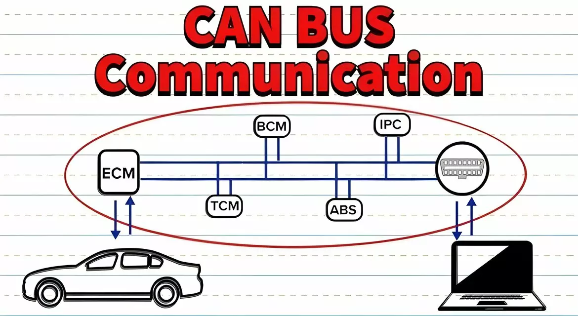
CAN bus is extensively used in vehicles for communication between various electronic control units (ECUs) such as the engine control module (ECM), transmission control module (TCM), anti-lock braking system (ABS), airbag system, and more. It facilitates real-time data exchange, enabling functionalities like engine management, transmission control, climate control, entertainment systems, and diagnostics.
Industrial Automation:
CAN bus is used in industrial automation for communication between programmable logic controllers (PLCs), sensors, actuators, and other devices on the factory floor. It allows for efficient control and monitoring of manufacturing processes, reducing wiring complexity and enabling real-time data transmission.
Medical Devices:
CAN bus is employed in various medical devices and equipment for communication between different modules, sensors, and control units. It ensures reliable and efficient data exchange in applications such as patient monitoring systems, diagnostic equipment, and medical imaging devices.
Marine and Aerospace:
CAN bus is utilized in marine and aerospace applications for communication between different subsystems, including engine control, navigation systems, instrumentation, and more. It provides a robust and reliable communication network even in harsh environments.
Home Automation:
CAN bus finds application in home automation systems for connecting and controlling various devices such as lighting, HVAC (heating, ventilation, and air conditioning), security systems, and appliances. It enables centralized control and monitoring of these devices.
Heavy Machinery and Agricultural Equipment:
CAN bus is used in heavy machinery and agricultural equipment for communication between different systems such as engine management, hydraulic control, GPS navigation, and monitoring systems. It enhances efficiency, productivity, and diagnostics.
Railway Systems:
CAN bus is employed in railway systems for communication between different subsystems including train control, traction control, braking systems, and passenger information systems. It enables reliable and efficient data exchange in both rolling stock and infrastructure.
Telematics and Fleet Management:
CAN bus is utilized in telematics systems for monitoring and managing fleets of vehicles. It enables real-time tracking of vehicle location, performance monitoring, remote diagnostics, and fleet optimization.
Energy Management:
CAN bus is used in energy management systems for communication between different components such as smart meters, inverters, energy storage systems, and grid infrastructure. It enables efficient control and monitoring of energy flow and consumption.
These are just a few examples of the wide-ranging applications of the CAN bus communication protocol across various industries, highlighting its versatility and reliability in enabling communication between different devices and systems.