What is Modbus Communication Protocol
Communication technologies Computer Science Electronics tutorial Internet of things IOT

Modbus Communication Protocol for Industrial Machines

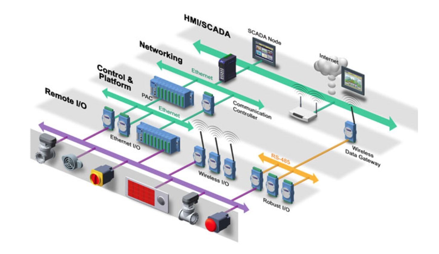
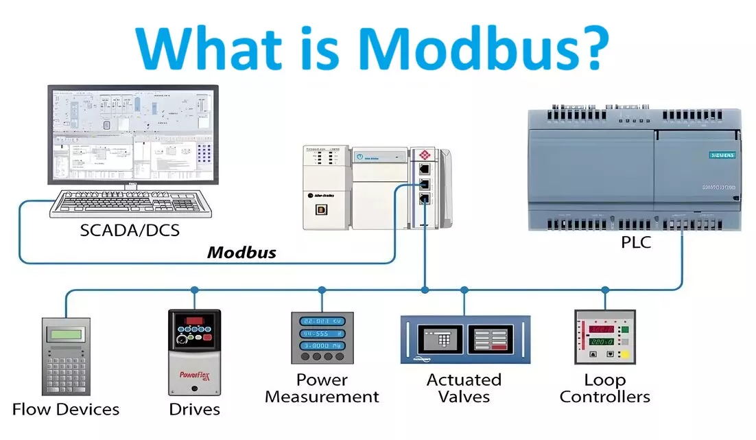
Modbus Communication Protocol is commonly used in industrial automation systems to exchange data between devices. It’s a simple and robust protocol, often used for connecting electronic devices such as programmable logic controllers (PLCs), remote terminal units (RTUs), sensors, and actuators.

Modbus Protocol History:

The Modbus communication protocol has a rich history dating back to the late 1970s. Here’s a brief overview of its evolution:

Development of Modbus by Modicon (1979):

Modbus was developed by Modicon (now part of Schneider Electric) in 1979 for its programmable logic controllers (PLCs). The aim was to create a simple and efficient communication protocol for industrial automation.

Modbus/RTU (Remote Terminal Unit):

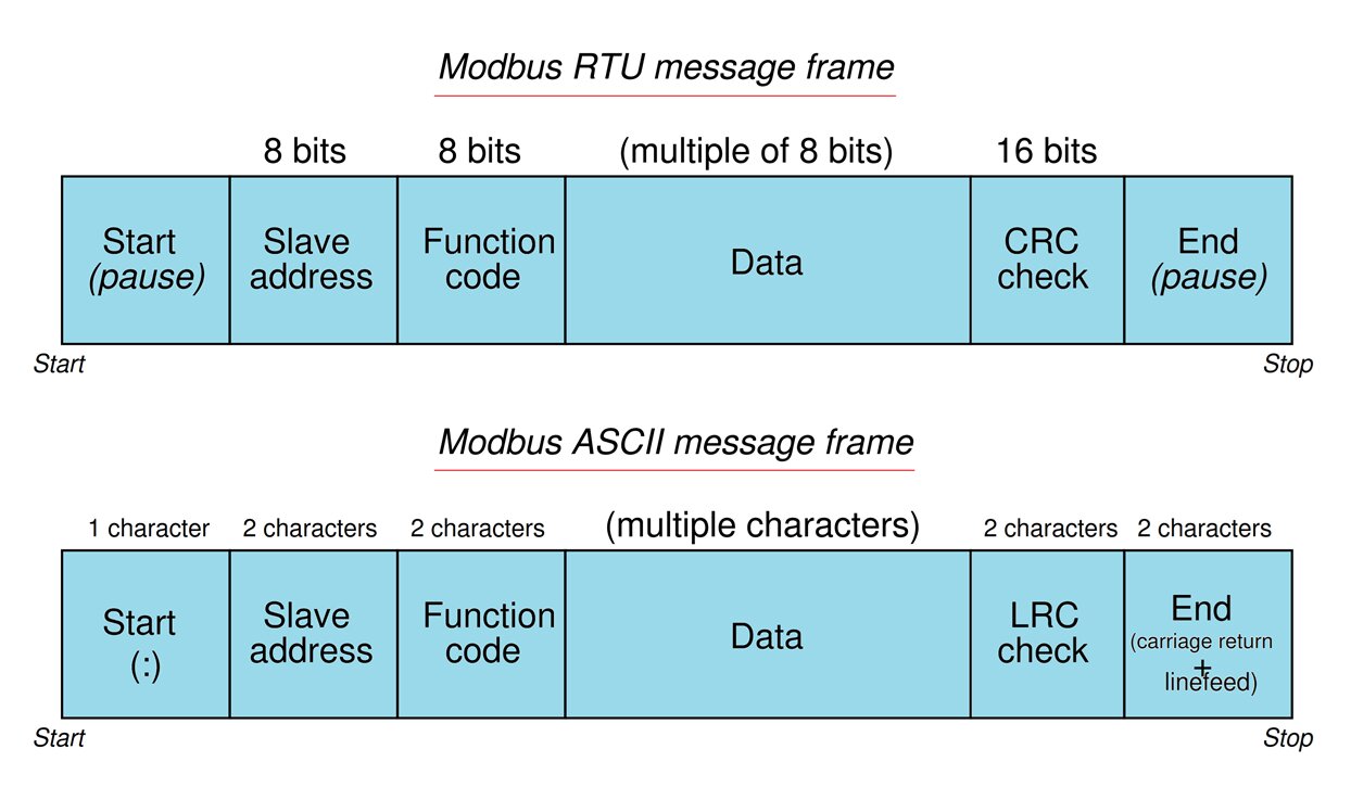
Modbus/RTU, introduced in 1979, is the most common implementation. It uses binary coding for communication and includes error-checking using CRC (Cyclic Redundancy Check).

Modbus/ASCII:

Modbus/ASCII was introduced as an alternative to RTU. It uses ASCII characters for communication, making it more human-readable. Each 8-bit byte is represented as two ASCII characters.

Modbus/TCP (Transmission Control Protocol):

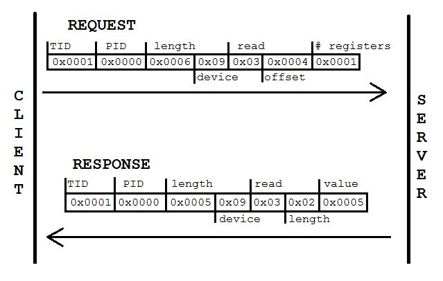
Modbus/TCP, developed later, allows Modbus communication over Ethernet networks. It utilizes the TCP/IP protocol suite, enabling communication between devices over standard Ethernet infrastructure.

Standardization (2004):

In 2004, the Modbus Organization (now Modbus-IDA Group) was formed to oversee the standardization and promotion of Modbus protocols. This organization ensures interoperability and maintains the Modbus specifications.

Expansion and Adoption:

Modbus has gained widespread adoption in various industries due to its simplicity, reliability, and interoperability. It’s used in industrial automation, building automation, energy management systems, and more.

Modbus Plus:

Modbus Plus is an extension of the original Modbus protocol, developed by Modicon. It adds features like token-passing and higher speed for larger-scale industrial networks.

Modbus Variants:

Over time, several variants and extensions of Modbus have been developed to address specific needs, such as Modbus/UDP (User Datagram Protocol) for lightweight communication and Modbus over Serial Line for specialized serial communication.

Despite being over four decades old, Modbus remains widely used and relevant in industrial automation due to its simplicity, versatility, and robustness. Its longevity can be attributed to its open nature, ease of implementation, and ongoing support from the industrial automation community.

Architecture of Modbus Communication Protocol:

Master-Slave Architecture: Modbus follows a master-slave architecture, where a single master device communicates with one or more slave devices. The master initiates transactions, and slaves respond to requests from the master. Here’s a breakdown of its architecture: 

Types of Messages:

Modbus supports different types of messages:

Read: The master requests data from one or more slaves.

Write: The master sends data to one or more slaves.

Read/Write: The master requests data from one slave and writes data to another slave in a single transaction.

Master Device:

  • The master device initiates communication and controls the data exchange process.
  • It sends requests to read or write data to one or more slave devices.
  • In a Modbus network, there can be only one master device.

Slave Devices:

  • Slave devices respond to requests from the master.
  • They typically include sensors, actuators, PLCs, or other devices that gather or control data.
  • Each slave device has a unique address on the network.

Communication Modes:

Serial Communication (RS-232/RS-485):

ASCII: Data is transmitted as ASCII characters.

  • Uses Modbus/RTU or Modbus/ASCII protocols.
  • Data is transmitted in binary format with error-checking (CRC).
  • Typically used for short-distance communication within industrial environments.
  • Supports multi-drop configuration where multiple devices share the same communication line.

Ethernet Communication (Modbus/TCP):

  • Utilizes TCP/IP protocol suite for communication over Ethernet networks.
  • Allows for higher data transfer rates and longer distances compared to serial communication.
  • Supports multiple master and slave devices in a network.

Addressing:

  • Each slave device is assigned a unique address ranging from 1 to 247 in Modbus/RTU or Modbus/ASCII modes.
  • In Modbus/TCP, addresses are typically associated with IP addresses.

Function Codes:

  • Function codes specify the type of action to be performed by the slave device.
  • Common function codes include reading and writing data, controlling outputs, and retrieving diagnostic information.
  • Read Coils (FC1)
  • Read Discrete Inputs (FC2)
  • Read Holding Registers (FC3)
  • Read Input Registers (FC4)
  • Write Single Coil (FC5)
  • Write Single Register (FC6)
  • Write Multiple Coils (FC15)
  • Write Multiple Registers (FC16)

Data Representation:

  • Data is typically represented in binary format.
  • Depending on the function code and the data being transmitted, Modbus supports various data formats such as integers, floating-point numbers, and bits.

Error Checking:

  • Modbus includes error-checking mechanisms to ensure data integrity.
  • Modbus/RTU uses CRC (Cyclic Redundancy Check) for error detection.
  • Modbus/ASCII uses LRC (Longitudinal Redundancy Check) for error detection.

Overall, Modbus’s architecture is designed to be simple, robust, and suitable for use in industrial automation applications. It provides an efficient means of communication between devices while allowing for easy integration and scalability.

Mod Bus Packet Format:

Modbus ASCII and RTU Message Frame

1. Modbus/RTU Packet Format:

In Modbus/RTU mode, data is transmitted in binary format. Each packet consists of the following components:

  • Address: 1 byte, specifying the address of the slave device (1 to 247).
  • Function Code: 1 byte, indicating the type of action to be performed.
  • Data: Variable length, depending on the function code and the specific request or response.
  • CRC (Cyclic Redundancy Check): 2 bytes, providing error-checking for the entire packet.

The packet format can be summarized as follows:

Address Function Code Data CRC
1 byte 1 byte Variable 2 bytes

2. Modbus/ASCII Packet Format:

In Modbus/ASCII mode, data is transmitted using ASCII characters, making it more human-readable. Each byte of the packet is represented by two ASCII characters (hexadecimal). The packet consists of:

  • Start Code: 1 character, indicating the start of the packet (‘:’ in ASCII).
  • Address: 2 characters (1 byte), specifying the address of the slave device.
  • Function Code: 2 characters (1 byte), indicating the action to be performed.
  • Data: Variable length, represented in hexadecimal.
  • LRC (Longitudinal Redundancy Check): 2 characters, providing error-checking.

The packet format can be summarized as follows:

Start Code Address Function Code Data LRC End of Line
1 char 2 chars 2 chars Variable 2 chars 2 chars (CR LF)

3. Modbus/TCP Packet Format:

In Modbus/TCP mode, data is encapsulated within TCP/IP packets. Each packet consists of:

  • Transaction Identifier: 2 bytes, used to match requests with responses.
  • Protocol Identifier: 2 bytes, always set to 0 for Modbus TCP.
  • Length: 2 bytes, indicating the number of bytes in the message following this field.
  • Unit Identifier: 1 byte, specifying the slave device address.
  • Function Code: 1 byte, indicating the action to be performed.
  • Data: Variable length, depending on the function code and request or response.

The packet format can be summarized as follows:

Transaction Identifier Protocol Identifier Length Unit Identifier Function Code Data
2 bytes 2 bytes 2 bytes 1 byte 1 byte Variable

These are the basic formats for Modbus packets in each mode. The specific structure may vary slightly depending on the implementation and additional features supported.

Mod Bus TCP Packet
Mod Bus TCP Packet

Modbus Registers and Functions:

In Modbus, registers are memory locations within a device that store data. There are four types of registers:

Coils

Used for digital output values, which can only be read from or written to as a single bit. Coils are typically used for controlling devices such as switches, valves, or relays.

Discrete Inputs:

Used for digital input values, which can only be read from. These inputs represent the state of physical devices like sensors or switches.

Input Registers:

Used for analog input values, such as temperature or pressure readings. Input registers are read-only.

Holding Registers:

Modbus Holding Registers is used for analog output values or other writable data. Holding registers can be read from and written to.Functions in Modbus specify the type of operation to be performed on registers. Some common Modbus functions include:

  • Read Coils (Function Code 01): Reads the status of coils (digital output values).
  • Read Discrete Inputs (Function Code 02): Reads the status of discrete inputs (digital input values).
  • Read Holding Registers (Function Code 03): Reads the contents of holding registers (analog output values or writable data).
  • Read Input Registers (Function Code 04): Reads the contents of input registers (analog input values).
  • Write Single Coil (Function Code 05): Writes a single bit (1 or 0) to a coil.
  • Write Single Register (Function Code 06): Writes a single value to a holding register.
  • Write Multiple Coils (Function Code 15): Writes multiple bits to coils.
  • Write Multiple Registers (Function Code 16): Writes multiple values to holding registers.

Each function code is associated with specific data addresses within the device. For example, Function Code 03 (Read Holding Registers) would typically include an address specifying which holding registers to read from, and a count indicating how many registers to read.

These functions and registers provide a versatile framework for exchanging data between Modbus devices, making it suitable for a wide range of industrial automation applications.

Modbus Request and Response:

Here’s a simplified representation of the Modbus request and response:

Modbus Request (Master to Slave):

Slave Address: 01
Function Code: 03 (Read Holding Registers)
Starting Address: 0001 (Address of the temperature register)
Quantity of Registers: 01 (Read one register, which contains the temperature value)
CRC: (Checksum for error checking)

Modbus Response (Slave to Master):

Slave Address: 01
Function Code: 03 (Read Holding Registers)
Byte Count: 02 (Number of bytes in the response)
Temperature Value: (Value read from the temperature register)
CRC: (Checksum for error checking)

This is a basic example, but in real-world applications, Modbus communication can involve more complex transactions, multiple devices, and different types of data.

Advantages of Modbus Communication Protocol:

  1. Simplicity: Modbus is straightforward and easy to implement, making it accessible for both developers and users.
  2. Versatility: It supports various data types and communication modes, allowing it to be used in diverse industrial applications.
  3. Interoperability: Modbus is widely supported across different devices and manufacturers, ensuring compatibility and easy integration.
  4. Cost-Effective: As a mature and widely-used protocol, Modbus-compatible devices are readily available at affordable prices.
  5. Reliability: Modbus has proven to be robust and reliable in industrial environments, with built-in error-checking mechanisms ensuring data integrity.
  6. Scalability: It can be used in small-scale systems as well as larger networks, with options like Modbus Plus for expanded capabilities.
  7. Open Standard: Being an open standard, Modbus specifications are freely available, encouraging innovation and development within the community.

Disadvantages of Modbus Communication Protocol:

  1. Limited Bandwidth: Modbus has relatively slow data transmission rates compared to newer protocols, which may not be suitable for high-speed applications.
  2. No Security Features: Originally designed for use in closed industrial networks, Modbus lacks built-in security features, making it vulnerable to unauthorized access and attacks when used over public networks like the internet.
  3. Limited Address Space: The addressing scheme of Modbus limits the number of devices that can be connected in a single network, which can be a constraint in larger installations.
  4. No Built-in Support for Complex Data Types: While it supports various data types, Modbus doesn’t inherently support complex data structures, which may require additional handling for more advanced applications.
  5. Limited Error Recovery: Although Modbus includes error-checking mechanisms, it lacks sophisticated error recovery features, which may result in data loss or corruption if errors occur frequently.
  6. Not Real-Time: Modbus is not a real-time protocol RTP, so it may not be suitable for applications requiring strict timing constraints.

Despite these limitations, Modbus remains widely used and preferred in many industrial applications due to its simplicity, reliability, and long-standing presence in the field.

Applications of Modbus Communication Protocol:

Modbus communication protocol finds applications across various industries, primarily in industrial automation and control systems. Here are some common applications:
Applications of Mod Bus Protocol

SCADA Systems:

Modbus is extensively used in Supervisory Control and Data Acquisition (SCADA) systems for monitoring and controlling industrial processes. SCADA systems communicate with PLCs and other devices using Modbus to collect data and issue control commands.

PLC Communication:

Programmable Logic Controllers (PLCs) often use Modbus for communication with sensors, actuators, and other devices on the factory floor. This allows for real-time monitoring and control of manufacturing processes.

Building Automation:

Modbus is used in building automation systems for controlling HVAC (Heating, Ventilation, and Air Conditioning), lighting, security systems, and other building functions. It enables centralized control and monitoring of building systems.

Energy Management Systems:

In energy management systems, Modbus is used to gather data from energy meters, sensors, and other devices to monitor energy consumption, optimize energy usage, and identify areas for improvement.

Remote Monitoring and Control:

Modbus enables remote monitoring and control of devices and processes in various industries. For example, it’s used in remote terminal units (RTUs) to collect data from remote locations such as oil and gas pipelines, water treatment plants, and electrical substations.

Industrial IoT (IoT):

With the rise of Industrial Internet of Things (IIoT), Modbus is used to connect legacy industrial equipment to modern IoT platforms. It allows older devices to send data to cloud-based systems for analysis and decision-making.

Sensor Networks:

Modbus is employed in sensor networks for collecting data from temperature sensors, pressure sensors, flow meters, and other industrial sensors. This data can be used for process optimization, predictive maintenance, and quality control.

Integration with HMI and SCADA Software:

Human Machine Interface (HMI) and SCADA software often support Modbus communication, allowing operators to visualize data, create custom dashboards, and control industrial processes.

Home Automation:

In addition to industrial applications, Modbus is also used in home automation systems for controlling home appliances, lighting, security systems, and more.

Overall, the versatility and simplicity of Modbus make it a widely adopted communication protocol in various automation and control applications.

What is a Sensor? Types of Sensors, Classification & Applications


Leave a Reply

Your email address will not be published. Required fields are marked *