An induction heater circuit is a type of device used to heat conductive materials by inducing electromagnetic currents within the material. These heaters are commonly used in industrial applications for processes such as metal melting, forging, brazing, and heat treatment. They work based on the principles of electromagnetic induction discovered by Michael Faraday.
Induction Heater Circuit Working:
Electromagnetic Coil:
The core component of an induction heater is an electromagnetic coil made of copper or other conductive materials. This coil is usually wrapped around a core made of a ferromagnetic material such as iron.
Alternating Current (AC) Power Supply:
The coil is connected to an alternating current power supply. The AC current flowing through the coil generates a changing magnetic field around it.
Induced Eddy Currents:
When a conductive material is placed within the changing magnetic field generated by the coil, it induces electric currents within the material due to electromagnetic induction. These currents are called eddy currents.
Resistance Heating:
The induced eddy currents encounter resistance within the conductive material, causing it to heat up due to the Joule heating effect. The heat generated is proportional to the square of the current flowing through the material and its electrical resistance, as described by Joule’s law (H = I²*R).
Heating Target Material:
The target material to be heated is usually placed within or near the coil. As the eddy currents circulate through the material, it rapidly heats up to the desired temperature.
Control Circuit:
The control circuit regulates the operation of the induction heater, controlling factors such as power output, frequency, and temperature. It may include components such as microcontrollers, feedback sensors (e.g., thermocouples), and control algorithms to adjust the operation of the driver circuit based on the desired heating parameters.
Cooling System:
Induction heaters generate heat not only in the target material but also in the components of the induction heater circuit itself. Therefore, a cooling system is often necessary to dissipate heat and prevent overheating of critical components. This may involve the use of heat sinks, fans, or liquid cooling systems.
Overall, induction heaters provide efficient and precise heating of conductive materials without direct contact, making them suitable for a wide range of industrial applications where controlled heating is required.
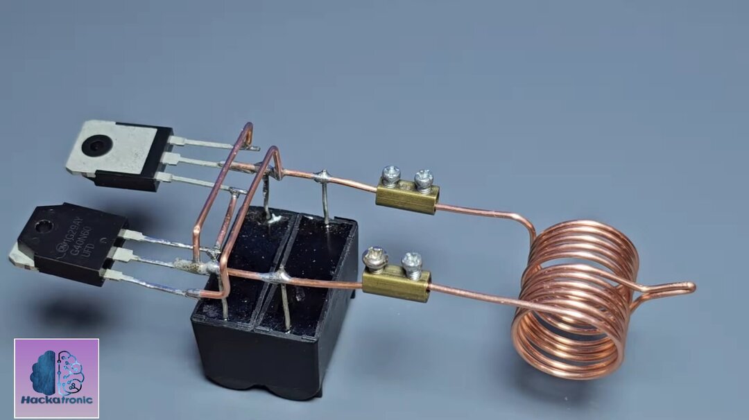
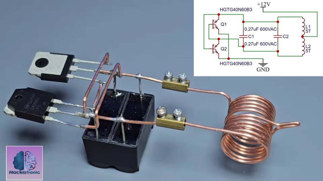
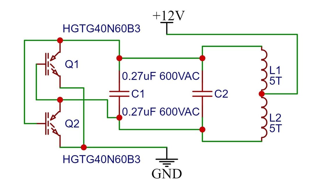
IGBT based Induction Heater Circuit Explained:
An induction heater circuit typically consists of several key components that work together to generate the alternating magnetic field necessary for electromagnetic induction and heat generation in the target material. Here is a basic circuit, let’s see overview of the components and their functions:
- IGBT HGTG40N60B3
- Film Capacitor 0.27uF 600VAC
- Inductor Coil
Power Supply:
The power supply provides the electrical energy needed to drive the induction heater circuit. Here we have used 12V power supply with enough amount of current.
Driver Circuit:
The driver circuit is responsible for controlling the flow of current through the induction coil. It consists of transistors, MOSFETs (Metal-Oxide-Semiconductor Field-Effect Transistors), or IGBTs (Insulated Gate Bipolar Transistors). we have used IGBT in our circuit. The IGBT act as an automatic switch, controlling the current flow. VI characteristics of IGBT
Induction Coil:
The induction coil is a crucial component of the induction heater circuit. It consists of a coil of wire wound around a core. When an alternating current flows through the coil, it generates a changing magnetic field around the coil, which induces eddy currents in the target material placed nearby. our induction coil has 5 + 5 turns.
Capacitors:
Capacitors are often used in induction heater circuits for power factor correction and resonance tuning. They help improve the efficiency of the circuit by ensuring that the power drawn from the power supply is used more effectively.
Resonant Tank Circuit:
The induction coil and capacitors are arranged in such a way that they form a resonant LC tank (inductor-capacitor) circuit. This circuit is tuned a specific frequency optimized for heating the target material efficiently. In our case it is around 182KHz.
The specific design and components of an induction heater circuit can vary depending on factors such as the power requirements, frequency of operation, and target material properties. Advanced induction heater circuits may incorporate additional features such as frequency modulation, power regulation, and safety mechanisms to ensure efficient and reliable operation.

Hi can I order one of these work
no