In this article you will learn how to make an LED chaser circuit using 555 timer IC and CD4017 counter IC. An LED chaser circuit is a simple electronic circuit that creates a sequential chasing effect by illuminating a series of LEDs one after the other. It is a popular project for hobbyists and electronics enthusiasts due to its ease of construction and the variety of effects that can be achieved.
Common set of components for LED Chaser circuit
There are many different ways to design an LED chaser circuit, but most of them use these elements.
- A power supply: This provides the necessary voltage to power the LEDs and other components in the circuit.
- A timer IC: This generates a series of pulses that control the sequencing of the LEDs.
- A series of LEDs: These are the lights that will create the chasing effect.
- Resistors: These are used to limit the current that flows through the LEDs.
- Additional components: Depending on the specific design of the circuit, additional components may be needed, such as diodes, capacitors, and transistors.
Components Required
- 555 Timer IC
- CD4017 Decade Counter IC
- LEDs 10 (we have used red)
- 1MΩ resistor
- 10kΩ resistor
- 220Ω resistor
- 50kΩ Potentiometer
- 0.22µF capacitor
- 10nF capacitor
- Jumper wires
- Breadboard or PCB
- 5V battery or power supply

Working of LED Chaser Circuit using 555 Timer and CD4017 IC
Our General type of LED chaser circuit uses a 555 timer IC. The 555 timer is a versatile IC that can be used in a variety of configurations, including astables, monostables, and bistables. In an LED chaser circuit, the 555 timer is configured as an astable oscillator, which means that it will generate a continuous stream of pulses. The frequency of the pulses can be adjusted by changing the values of the resistors and capacitors that are connected to the timer IC.
The pulses generated by the 555 timer are then used to control a series of transistors, which in turn switch the LEDs on and off. The transistors are connected in a chain, so that when one transistor is turned on, it also turns on the next transistor in the chain. This creates a cascading effect, in which the LEDs light up one after the other.
The speed of the chasing effect can be adjusted by changing the frequency of the pulses generated by the 555 timer. A higher frequency will result in a faster chasing effect, while a lower frequency will result in a slower chasing effect.
LED chaser circuits can be used in a variety of applications, including decorative lighting, automotive lighting, and safety lighting. They are also a popular project for hobbyists and electronics enthusiasts due to their ease of construction and the variety of effects that can be achieved.
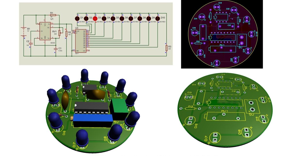
LED Chaser Circuit PCB Schematic
Here is the schematic of PCB, you can see that it’s a circular shape for showing a running circle of light.


As you can see, the circuit is quite simple and only requires a few components. It is a good project for beginners who are just starting to learn about electronics.

With a little creativity, you can modify this basic circuit to create a variety of different effects. For example, you could use different types of LEDs, such as red, green, and blue, to create a colorful chasing effect. You could also use more than one chain of transistors to create a more complex chasing pattern.
LED chaser circuits are a fun and easy way to learn about electronics. With a little practice, you can create your own unique and eye-catching designs.
