An XOR Gate (Exclusive OR Gate) is one of the most important logic gates in digital electronics. It performs a Boolean operation known as exclusive addition, where the output depends on the difference between input values.
In simple terms, an XOR gate produces an output HIGH (1) only when the inputs are different from each other. If all inputs are the same (either all LOW or all HIGH), the output becomes LOW (0).
XOR gates are widely used in digital systems where comparison, error detection, and bit-wise operations are required. They are essential in applications such as adders, parity checkers, encryption circuits, and digital communication systems.
They are especially important because XOR logic forms the foundation of binary arithmetic operations, making it a critical building block in processors and computational circuits.
- Related Articles:
- Types of Logic Gates with Symbol, Truth Table and IC Numbers
- Universal NOR Gate Truth Table with IC 7402 PIN Diagram
- NAND Gate Truth Table, Logic Circuit & IC 7400 Pin Diagram
- OR Gate: Symbol, Truth Table, Logic Circuit, and IC Numbers
- AND Gate: Symbol, Truth Table, Logic Circuit, and IC Numbers
- NOT Gate: Symbol, Truth Table, Logic Circuit, and IC Numbers
Symbol of XOR Gate
- Standard Symbol (ANSI)
- The most commonly used XOR gate symbol (ANSI standard) consists of:
- A shape similar to the OR gate
- An extra curved line at the input side (this distinguishes XOR from OR)
- Two or more input lines entering from the left
- One output line exiting from the right
- This additional curved line indicates the exclusive nature of the operation.
- The most commonly used XOR gate symbol (ANSI standard) consists of:
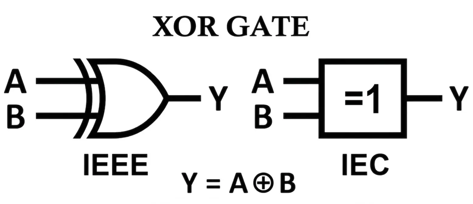
- IEC Symbol
- Represented as a rectangle
- Inside marking: =1 (means “exactly one input is HIGH”)
- Inputs enter from the left, output exits from the right
- Multi-Input Symbol
- Additional input lines can be added on the left
- Logic: Output is HIGH if an odd number of inputs are HIGH
- Terminal and Notation
- Inputs: A, B, C, D…
- Output: Y or Q
- Boolean expression: Y = A ⊕ B
- The symbol ⊕ represents the XOR (exclusive OR) operation
- Important Observations
- XOR gate outputs HIGH only for unequal inputs
- Unlike OR gate, it does not produce HIGH for all HIGH inputs
- It acts as a digital comparator for equality detection
- If a bubble is added at the output → it becomes an XNOR gate
- XOR is widely used in binary addition (Sum output of Half Adder)
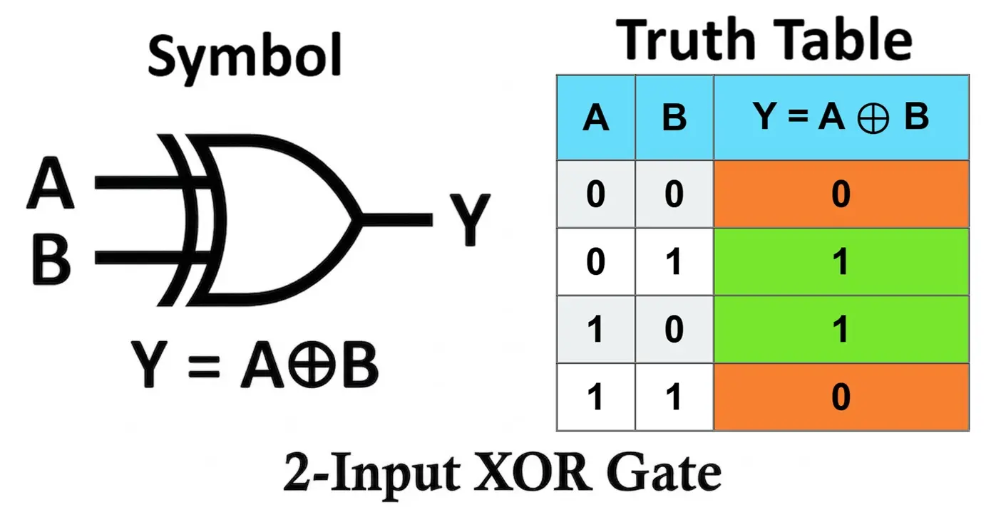
XOR Gate Truth Table
- Working Principle
- The XOR gate operates based on a selective condition:
- Output is HIGH (1) when inputs are different
- Output is LOW (0) when inputs are the same
- Unlike OR gate, XOR does not simply respond to HIGH inputs, it checks whether the inputs are unequal.
- The XOR gate operates based on a selective condition:
- Boolean Logic
- The XOR operation follows the Boolean expression: Y = A ⊕ B
- This is why it is called an exclusive logic gate, as it excludes the case where both inputs are the same.
- Key Condition:
- Inputs are different → Output = HIGH
- Inputs are same → Output = LOW
- If A = 0 and B = 1 → Y = 1
- If A = 1 and B = 0 → Y = 1
- If A = 0 and B = 0 → Y = 0
- If A = 1 and B = 1 → Y = 0
This makes the XOR gate highly useful in comparison and decision-based logic circuits.
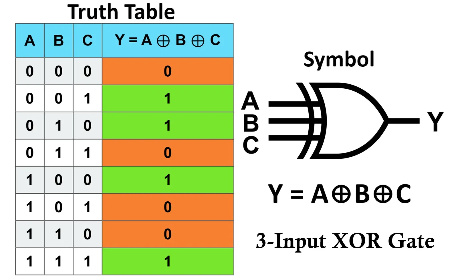
- Key Observation
- Output is HIGH if an odd number of inputs are HIGH
- Output is LOW if an even number of inputs are HIGH
- Extended Form: Y = A ⊕ B ⊕ C ⊕ D …
- Truth Table Insight
- XOR gate acts as a digital difference detector
- It is commonly used for bit comparison and parity checking
- Plays a key role in binary addition (sum output in adders)
- Multi-Input XOR Gates
- Can have more than 2 inputs
- Output depends on the parity (odd/even count of HIGH inputs)
- Widely used in:
- Error detection circuits
- Digital communication systems
- Arithmetic logic units (ALUs)
XOR Logic Circuits
Diode XOR Gate (Diode Transistor Logic)
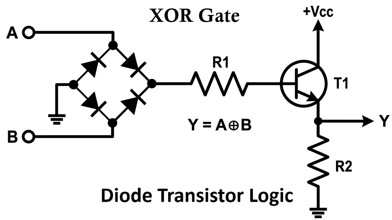
- Components
- Diodes (D1, D2, D3, D4)
- Transistor (T1)
- Resistors (pull-down resistors)
- Working
- XOR cannot be implemented using simple diode alone
- It requires a combination of AND, OR, and NOT behavior using diodes
- The circuit is designed such that:
- When inputs are different → a conduction path exists → output HIGH
- When inputs are same → no valid conduction path → output LOW
- Key Behavior
- Selective conduction paths allow output only for unequal inputs
- Uses multiple diode paths to enforce XOR condition
- Limitation
- Complex compared to diode OR/AND gates
- Voltage drops accumulate across multiple diodes
- Not suitable for precise or high-speed logic applications
Transistor XOR Gate (RTL / TTL Concept)
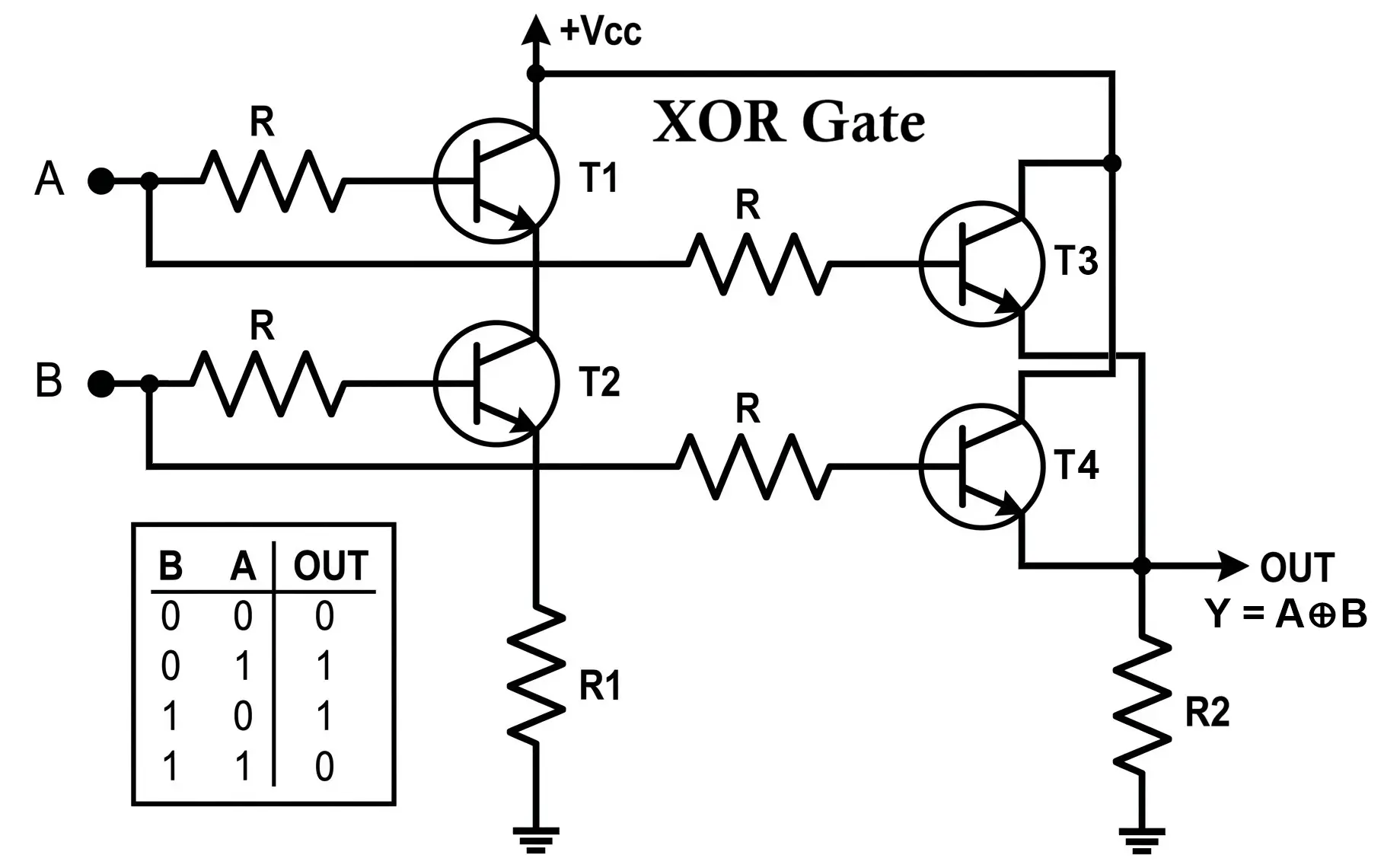
- Working Principle:
- Transistors act as switches
- Configured in a combination of series and parallel networks
- Operation
- When A ≠ B:
- One transistor path turns ON while the other remains OFF
- This creates a conduction path → output HIGH
- When A = B:
- Either both paths OFF or both ON in a way that cancels output
- Output remains LOW
- When A ≠ B:
- Key Insight
- XOR requires conditional switching, not just parallel conduction
- Combination of switching paths enforces difference detection
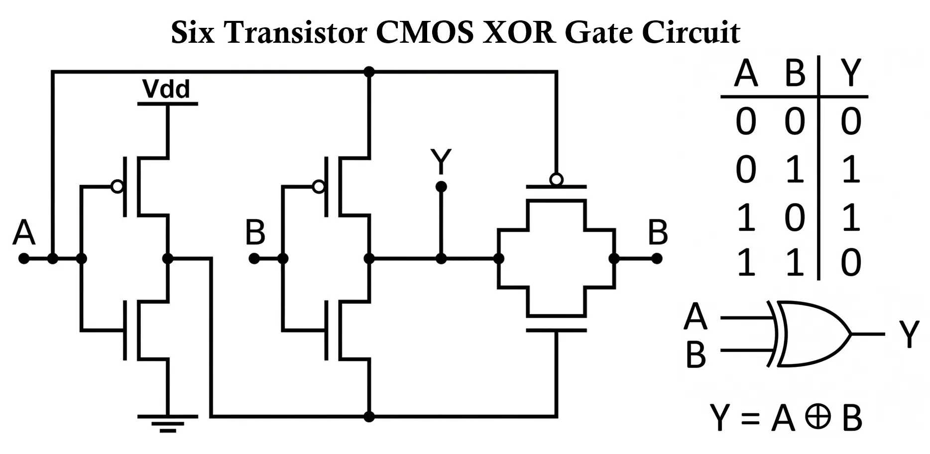
CMOS XOR Gate
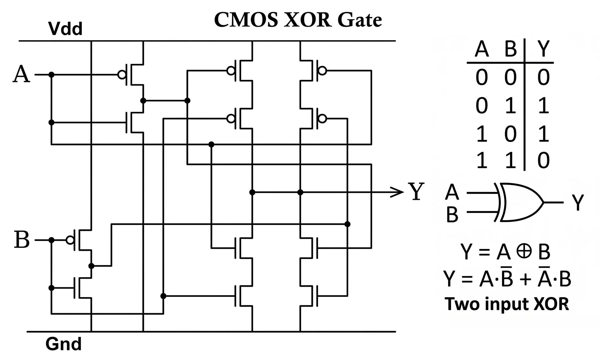
- Structure
- Uses both PMOS (pull-up network) and NMOS (pull-down network)
- More complex than basic gates due to XOR functionality
- Configuration
- PMOS and NMOS arranged in complementary symmetry
- Designed to produce HIGH output only for unequal inputs
- Working
- If A ≠ B: Proper PMOS/NMOS paths conduct → output HIGH
- If A = B: Either pull-up or pull-down dominates → output LOW
- Advantages
- Very low power consumption
- High noise immunity
- Widely used in modern ICs and VLSI systems
XOR Using AND, OR, NOT Gates
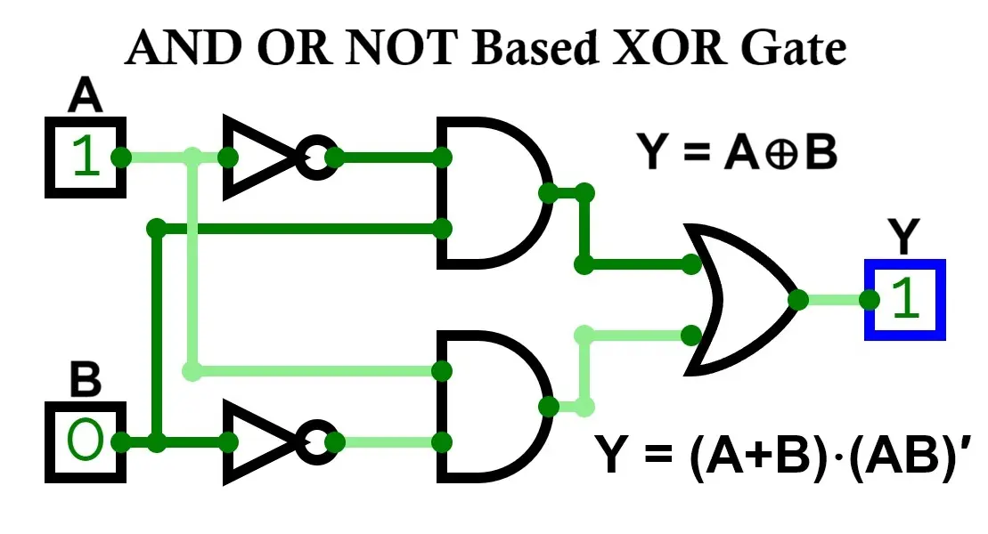
- Working
- First term (A̅B): HIGH when A = 0, B = 1
- Second term (AB̅): HIGH when A = 1, B = 0
- OR gate combines both → output HIGH when inputs differ
- Key Insight
- XOR is essentially a sum of two mutually exclusive conditions
- This is the most fundamental and widely taught implementation
NAND Based XOR Gate
- Boolean Expression
- The XOR function using only NAND gates can be expressed as:
- Y = (A NAND (A NAND B)) NAND (B NAND (A NAND B))
- This form is derived by systematically replacing AND, OR, and NOT operations with NAND equivalents.
- The XOR function using only NAND gates can be expressed as:
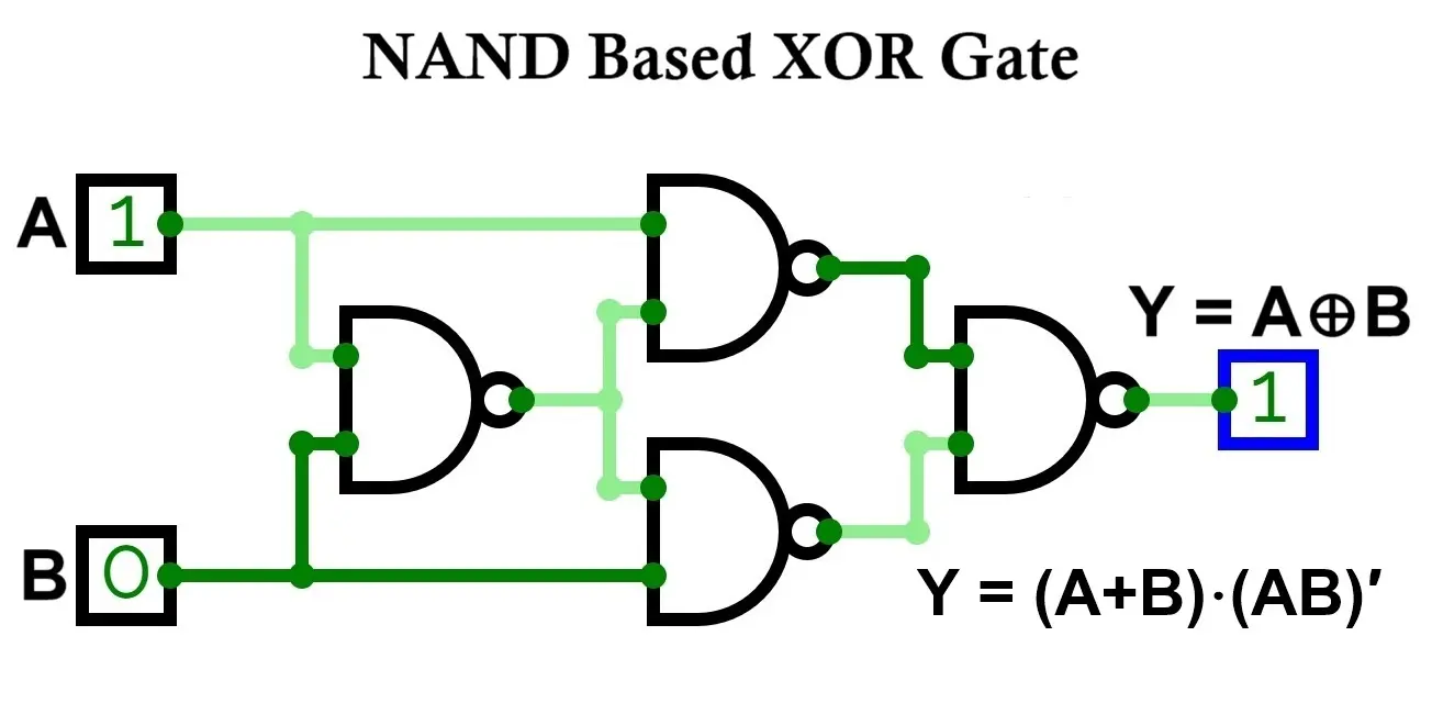
- Concept
- NAND is a universal gate
- XOR can be implemented using only NAND gates
- Requires 4 NAND gates
- Working
- Let: D = A NAND B
- Now:
- E = A NAND D
- F = B NAND D
- Output: Y = E NAND F
- When A ≠ B:
- Intermediate outputs create a valid HIGH path
- Final NAND produces HIGH output
- When A = B:
- Intermediate outputs cancel each other
- Final output becomes LOW
- Key Insight
- Efficient realization using minimal universal gates
- Widely used in TTL-based digital IC design
- Forms the basis of many optimized logic circuits
NOR Based XOR Gate
- Boolean Expression
- The XOR function using only NOR gates can be expressed as:
- Y = (A NOR (A NOR B)) NOR (B NOR (A NOR B))
- This expression is obtained by converting XOR into NOR-only logic using De Morgan’s laws and double inversion.
- The XOR function using only NOR gates can be expressed as:
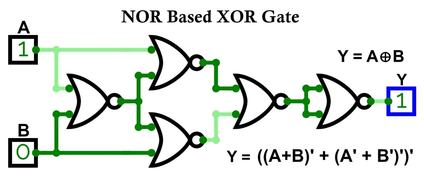
- Concept
- NOR is also a universal gate
- XOR can be built using only NOR gates
- Requires multiple NOR gates
- Slightly more complex than NAND implementation
- Working
- Let: D = A NOR B
- Now:
- E = A NOR D
- F = B NOR D
- Output: Y = E NOR F
- Uses layered inversion and recombination of signals
- Intermediate NOR stages generate required complemented terms
- Final NOR stage produces XOR output
- Key Insight
- Useful in CMOS implementations, where NOR structures are efficient
- Provides an alternative universal-gate realization of XOR
- Slightly higher gate count compared to NAND-based design
- Summary Insight
- XOR gate implementation is more complex than OR/AND gates
- It requires combination logic rather than simple conduction paths
- Widely implemented using:
- Basic gates (AND-OR-NOT)
- NAND-only or NOR-only logic
- CMOS structures in ICs
XOR IC Numbers and Details
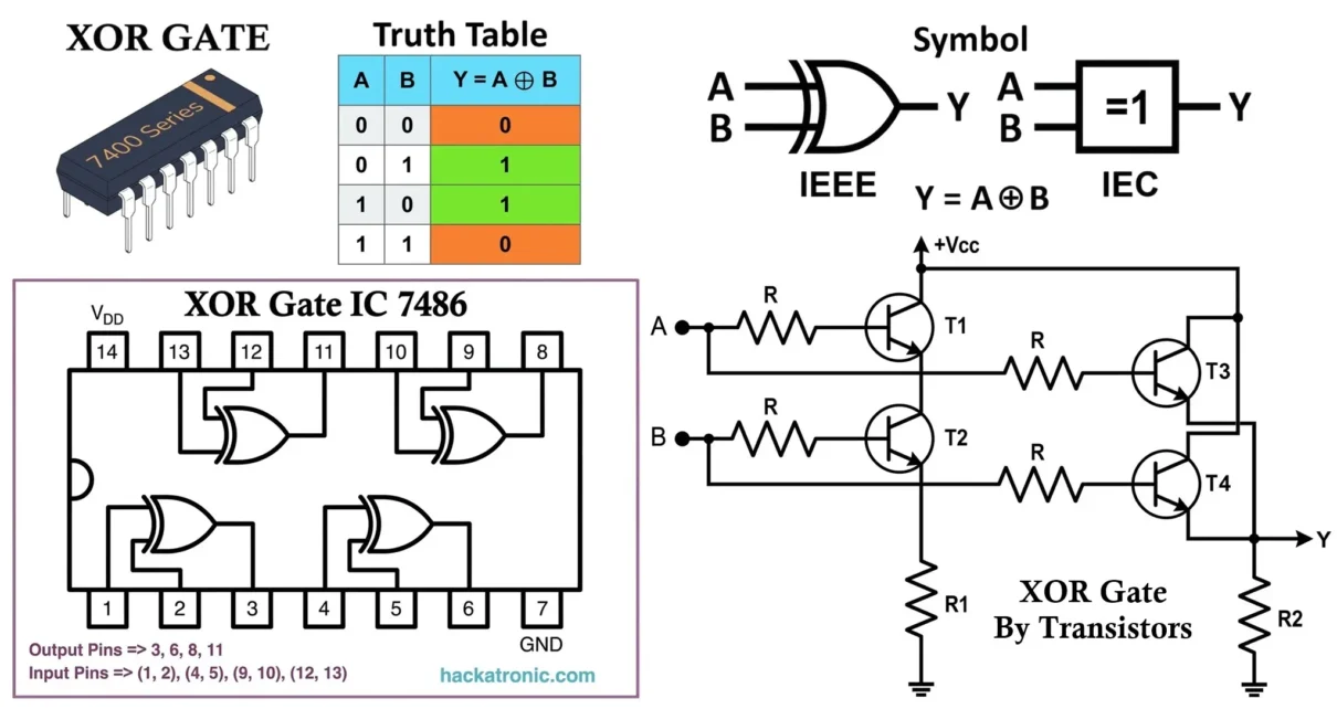
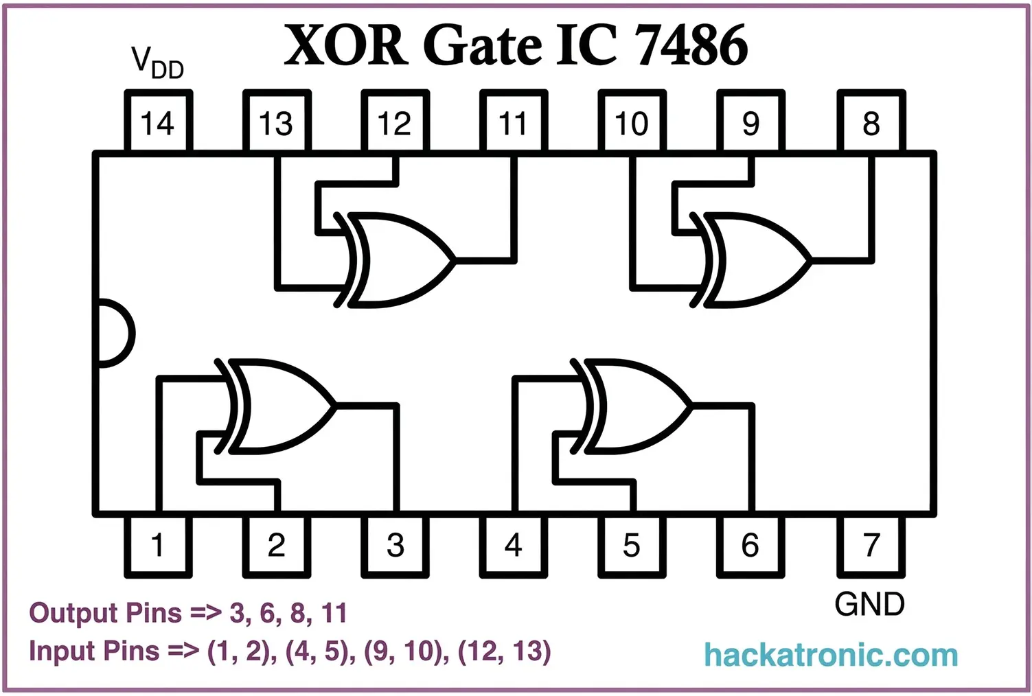
XOR Gate IC 7486
The 7486 XOR Gate IC is a widely used Quad 2-input XOR gate integrated circuit belonging to the TTL – Transistor-Transistor Logic family.
- Features
- Quad 2-input XOR gates (4 XOR gates inside)
- Technology: TTL (BJT-based)
- Propagation delay: ~10 ns
- Power consumption: ~2 mW per gate
- Supply voltage: 5V (fixed)
- Fan-out: ~10 TTL loads
- Pin Configuration
- Total pins: 14
- 4 XOR gates inside the IC:
- Gate 1: Pins 1, 2 → Output 3
- Gate 2: Pins 4, 5 → Output 6
- Gate 3: Pins 9, 10 → Output 8
- Gate 4: Pins 12, 13 → Output 11
- Power Pins:
- Pin 14: Vcc (+5V)
- Pin 7: GND
Key Characteristic: Each gate operates independently, enabling multiple XOR operations within a single IC, very useful in compact digital and arithmetic circuit designs.
74LS86 – Low-Power Schottky TTL XOR Gate
The 74LS86 belongs to the Low-Power Schottky (LS) TTL family, optimized for improved switching speed and reduced power consumption.
- Specifications:
- Technology: TTL with Schottky transistors
- Propagation delay: ~10 ns
- Power consumption: Moderate (~2 mW per gate)
- Supply voltage: 5V (fixed)
- Fan-out: ~10 TTL loads
Key Characteristic: Offers a good balance between speed and power, commonly used in traditional digital logic systems.
74HC86 – High-Speed CMOS XOR Gate
The 74HC86 is part of the High-Speed CMOS family, combining low power consumption with high switching performance.
- Specifications:
- Technology: CMOS
- Supply voltage: 2V to 6V
- Power consumption: Very low (µW range)
- Propagation delay: ~8–15 ns
- Input impedance: Very high
Key Characteristic: Ideal for modern low-power digital systems with excellent noise immunity and flexibility.
74HCT86 – TTL-Compatible CMOS XOR Gate
The 74HCT86 is a CMOS-based XOR IC designed to be compatible with TTL input voltage levels.
- Specifications:
- Technology: CMOS with TTL input compatibility
- Supply voltage: Typically, 5V
- Power consumption: Very low
- Propagation delay: Similar to HC series
- Input Levels: LOW ≤ 0.8V, HIGH ≥ 2V
Key Characteristic: Allows seamless interfacing between TTL and CMOS circuits without requiring additional level-shifting components.
CD4070 – CMOS Quad XOR Gate
The CD4070 belongs to the 4000-series CMOS family, optimized for wide voltage range and ultra-low power operation.
- Specifications:
- Technology: CMOS (4000 series)
- Supply voltage: 3V to 15V
- Power consumption: Extremely low
- Propagation delay: ~60–200 ns (voltage dependent)
- Noise immunity: High
Key Characteristic: Best suited for battery-powered and low-frequency applications where power efficiency is more important than speed.
IC Comparison Table
| IC Number | Technology | Voltage | Speed | Power |
|---|---|---|---|---|
| 7486 | TTL | 5V | Medium | Medium |
| 74LS86 | TTL (LS) | 5V | High | Low |
| 74HC86 | CMOS | 2–6V | High | Very Low |
| 74HCT86 | CMOS + TTL | 5V | High | Low |
| CD4070 | CMOS | 3–15V | Medium | Very Low |
Timing and Practical Considerations
- Propagation Delay
- Time taken for output to respond to a change in input
- TTL XOR gates: ~10 ns
- CMOS XOR gates: ~8–15 ns (HC series), higher in 4000 series
- Important Note: XOR gates generally have slightly higher propagation delay than simple gates (AND/OR) due to their internal complexity.
- Critical in high-speed digital circuits
- Affects timing in adders, ALUs, and clocked systems
- Time taken for output to respond to a change in input
- Fan-In and Fan-Out
- Fan-In
- Number of inputs an XOR gate can accept
- Typically limited to 2 or 3 inputs in standard ICs
- Fan-Out
- Number of logic inputs the output can drive
- TTL: ~10 loads
- CMOS: Higher due to high input impedance
- Key Insight
- XOR gates are less commonly used with very high fan-in due to complexity
- Multi-input XOR is often implemented using cascaded stages
- Fan-In
- Noise Margin
- CMOS > TTL
- CMOS XOR gates provide better immunity to noise and signal disturbances
- Importance
- Crucial in communication systems and high-speed digital circuits
- Ensures reliable logic transitions
- Power Consumption
- TTL: Higher power consumption
- CMOS: Very low power (µW range)
- Key Insight
- CMOS XOR gates are preferred for:
- Battery-powered devices
- Portable electronics
- Embedded systems
- CMOS XOR gates are preferred for:
XOR Logic Example
- Parity Checker (Error Detection)
- Consider a system with two inputs:
- Data bit (A)
- Parity bit (B)
- Consider a system with two inputs:
- Output (Y) = Error detection signal
- If inputs are different → Output HIGH (error detected or odd parity)
- If inputs are same → Output LOW
| A | B | Y |
|---|---|---|
| 0 | 0 | 0 |
| 0 | 1 | 1 |
| 1 | 0 | 1 |
| 1 | 1 | 0 |
Key Insight: XOR acts as a parity generator/checker, widely used in communication systems.
- Half Adder (Binary Addition)
- A = First bit
- B = Second bit
- Sum output (S) = A ⊕ B
- Behavior
- Output HIGH when inputs are different
- Forms the sum output in binary addition
XOR Logic Circuit Implementations
- Using Switches (Mechanical Logic)
- Requires combination of switches (series + parallel)
- Designed to allow current only when inputs differ
- Insight
- More complex than OR logic
- Rarely used in simple mechanical systems
- Using Relay Logic
- Combination of relay contacts arranged to detect unequal inputs
- Output energizes only for XOR condition
- Used in specialized industrial logic systems
- Using FPGA / Digital Systems
- Implemented using HDL: assign Y = A ^ B;
- Used in FPGA design, ASIC circuits and microprocessor logic
Applications
- In Digital Electronics
- Half Adders and Full Adders
- Parity Generators and Checkers
- Subtractors
- Comparators
- In Computing Systems
- Arithmetic Logic Units (ALUs)
- Error detection and correction
- Data encryption (bitwise XOR operations)
- Bit manipulation operations
- In Communication Systems
- Data transmission error checking
- Encoding and decoding schemes
- In Everyday Electronics
- Digital calculators
- Microcontrollers
- Embedded systems
Advantages
- Essential for arithmetic operations
- Enables error detection (parity checking)
- Acts as a digital comparator
- Widely used in processors and communication systems
- Flexible in logic design
Limitations
- More complex than basic gates (AND, OR)
- Higher propagation delay
- Requires multiple gates for implementation
- Not suitable as a standalone universal logic element
XOR Gate vs AND Gate vs OR Gate vs NOT Gate
| Feature | XOR Gate | OR Gate | AND Gate | NOT Gate |
|---|---|---|---|---|
| Boolean Expression | A ⊕ B | A + B | A · B | A̅ |
| Output Condition | Inputs different | Any input HIGH | All inputs HIGH | Inverts input |
| Output Behavior | Selective | Flexible | Strict | Opposite |
- Key Differences:
- XOR Gate: Output HIGH only when inputs are different
- OR Gate: Output HIGH if any input is HIGH
- AND Gate: Output HIGH only if all inputs are HIGH
- NOT Gate: Reverses input logic
Conclusion
The XOR gate is a fundamental and highly important logic gate in digital electronics that performs exclusive logic operations. It outputs HIGH only when inputs are different, making it essential for comparison, arithmetic, and error detection systems.
Key Insights
- XOR gate is a difference detector and parity checker
- Core component in:
- Adders (binary arithmetic)
- Error detection systems
- Digital communication
- Truth table defines exclusive logic behavior
- Implemented using:
- Basic gates (AND-OR-NOT)
- NAND/NOR logic
- CMOS technology
- Available in various IC families:
- 7486, 74LS86, 74HC86, CD4070
From binary addition in processors to error detection in communication systems, XOR gates play a critical role in modern digital electronics. Understanding their working, implementation, and applications is essential for mastering both fundamental and advanced digital logic design.
Types of Logic Gates with Symbol, Truth Table and IC Numbers
AND Gate: Symbol, Truth Table, Logic Circuit, and IC Numbers
NOT Gate (Inverter): Symbol, Truth Table, Logic Circuit, and IC Numbers
Classification of Digital Logic Families with Characteristics and Applications
