This article explores various types of PCB materials, their composition, electrical and mechanical properties, advantages, disadvantages, and applications in different industries.
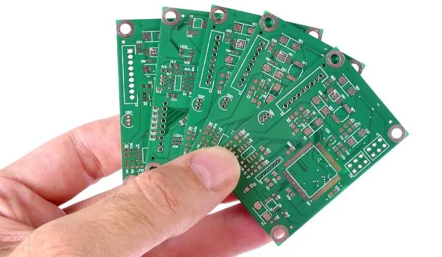
Printed Circuit Boards (PCBs) form the backbone of almost every modern electronic device — from small gadgets to industrial machines and communication systems. The performance, durability, and reliability of a PCB depend largely on the type of material used for its substrate and dielectric layers.
Choosing the right PCB material is crucial because it affects parameters like signal integrity, mechanical strength, heat resistance, frequency response, and cost.
For high-quality PCB manufacturing and assembly services, visit NextPCB.
1. Introduction to PCB Materials
A typical PCB is composed of several layers:
- Substrate (Base Material): Provides mechanical support.
- Copper Foil: Conductive layer forming electrical pathways.
- Solder Mask: Protects copper traces from oxidation and short circuits.
- Silkscreen: For labeling and component identification.
The substrate and dielectric materials determine how all the types of PCB materials will perform under different electrical, mechanical, and thermal conditions.
Key properties that define PCB materials include:
| Property | Description | Typical Range |
|---|---|---|
| Dielectric Constant (Dk) | Determines how fast electrical signals travel. Lower Dk = higher signal speed. | 2.0 – 10 |
| Dissipation Factor (Df) / Loss Tangent | Represents energy loss as heat during signal transmission. Lower Df = lower loss. | 0.0002 – 0.035 |
| Glass Transition Temperature (Tg) | The temperature where the material softens. High Tg = better thermal stability. | 100°C – 260°C |
| Coefficient of Thermal Expansion (CTE) | Rate of expansion with heat; mismatch can cause layer cracking. | 10–70 ppm/°C |
| Thermal Conductivity | Heat dissipation capacity. | 0.2–200 W/mK |
| Moisture Absorption | Ability to resist humidity; affects insulation. | 0.02–1.5% |
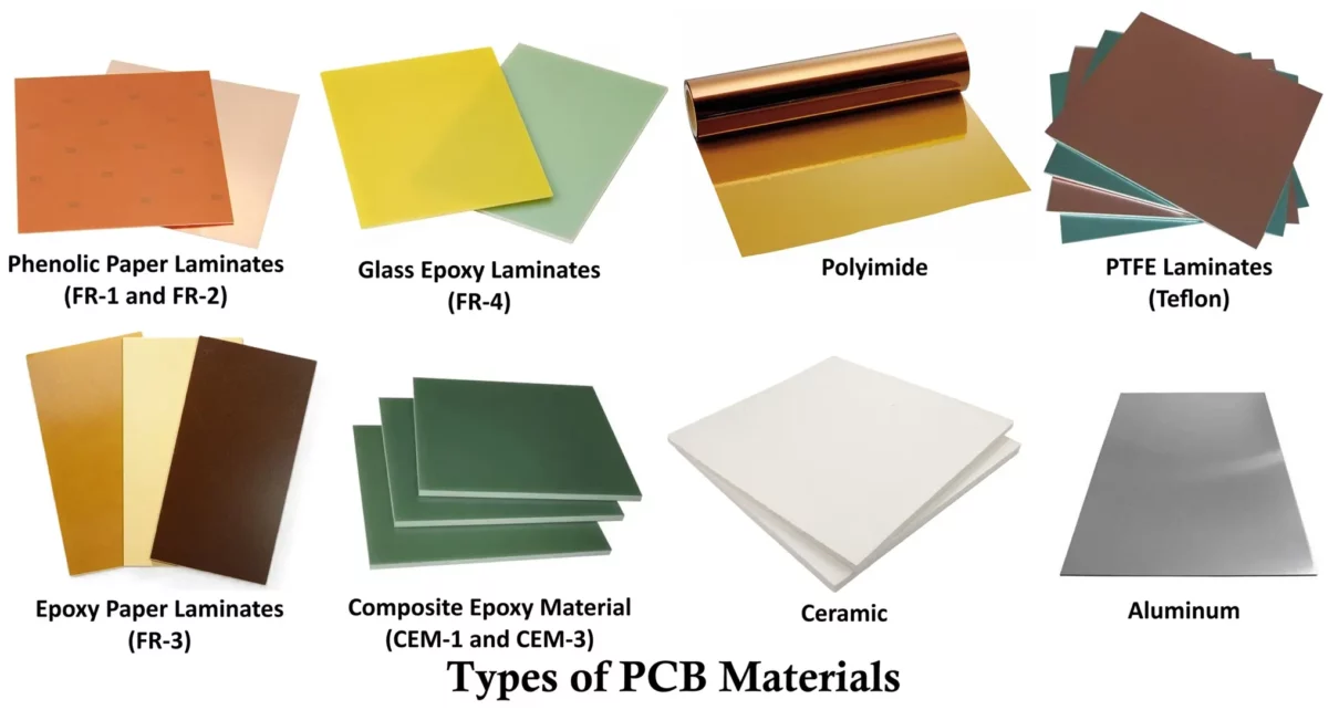
2. Types of PCB Materials
Let’s explore all the types of PCB materials with their composition, properties, advantages, disadvantages and applications.
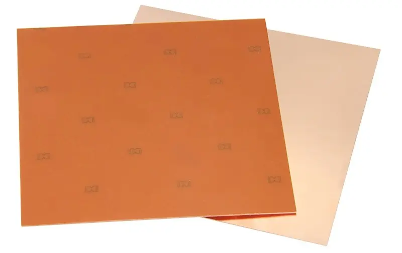
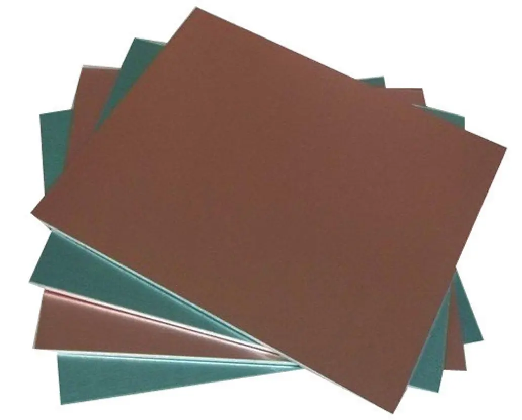
2.1 FR-1 and FR-2 (Phenolic Paper Laminates)
Composition:
- Made from paper reinforced with phenolic resin.
- “FR” stands for Flame Retardant.
- FR-1 and FR-2 differ mainly in their glass transition temperature.
Properties:
- FR-1: Tg ≈ 130°C
- FR-2: Tg ≈ 105°C
- Good mechanical strength for low-cost applications.
- Moderate insulation resistance.
Advantages:
- Low cost and easily available.
- Simple manufacturing process.
- Suitable for single-sided PCBs.
Disadvantages:
- Poor thermal and moisture resistance.
- Not suitable for multi-layer or high-frequency circuits.
- Limited mechanical strength compared to fiberglass laminates.
Applications:
- Low-cost consumer electronics such as:
- Calculators
- Toys
- Power adapters
- Small household appliances
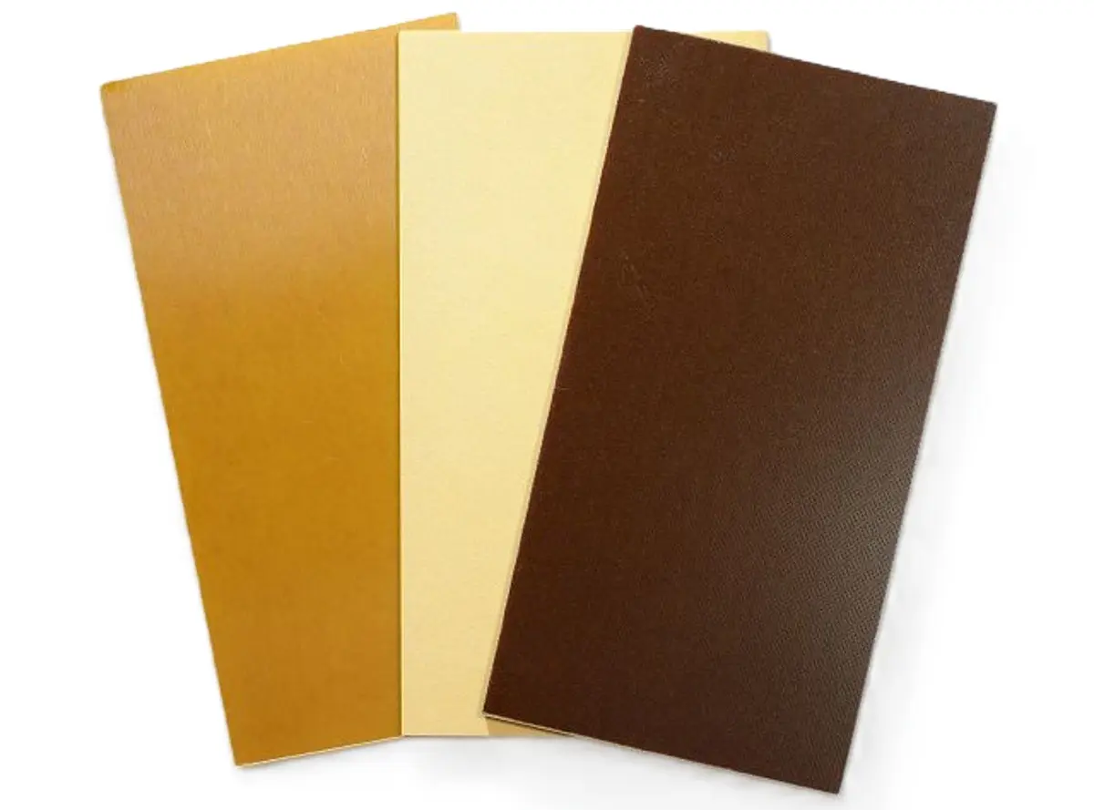
2.2 FR-3 (Epoxy Paper Laminate)
Composition:
- Paper base impregnated with epoxy resin instead of phenolic.
- Offers improved bonding and electrical insulation.
Properties:
- Tg ≈ 130°C
- Better electrical performance than FR-2.
- Higher mechanical stability and moisture resistance.
Advantages:
- Improved performance over FR-2.
- Cost-effective for low-power applications.
Disadvantages:
- Still not suitable for double-sided or multilayer boards.
- Limited heat resistance.
Applications:
- Telecommunication devices
- Power supply boards
- Simple consumer electronics
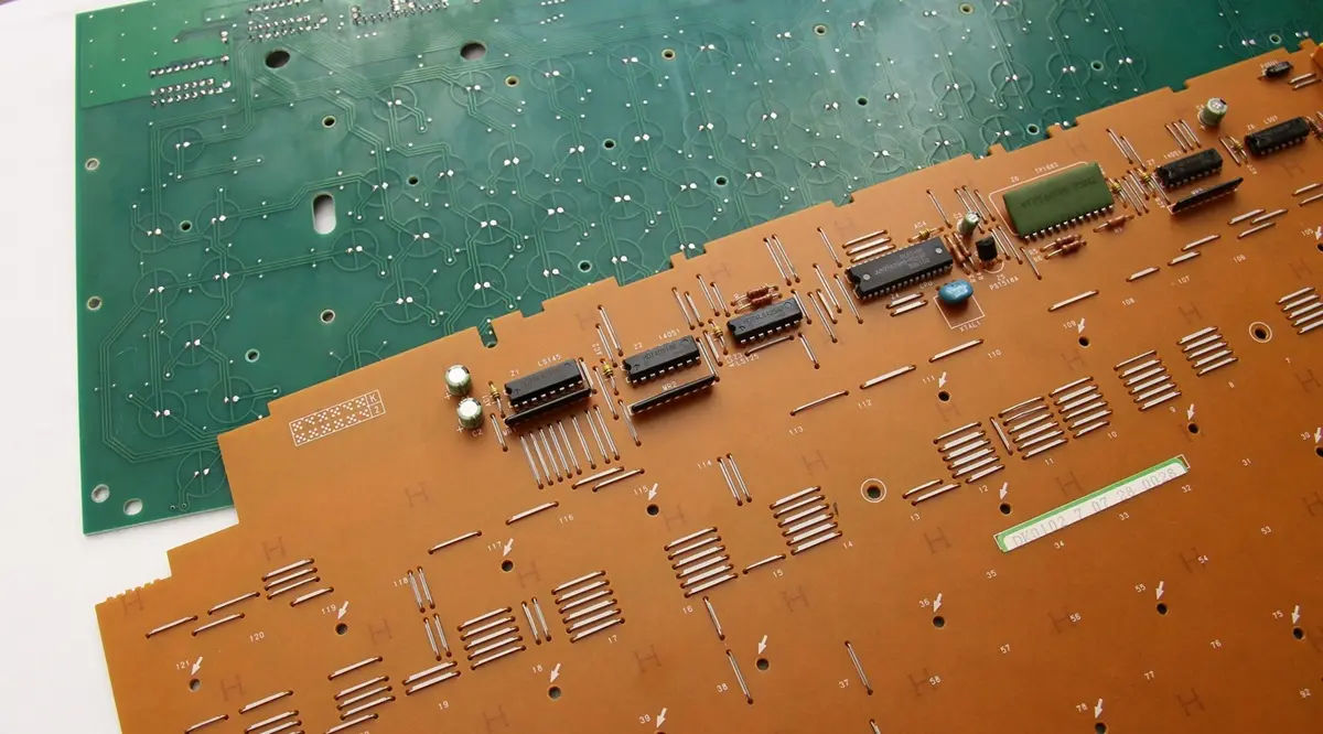
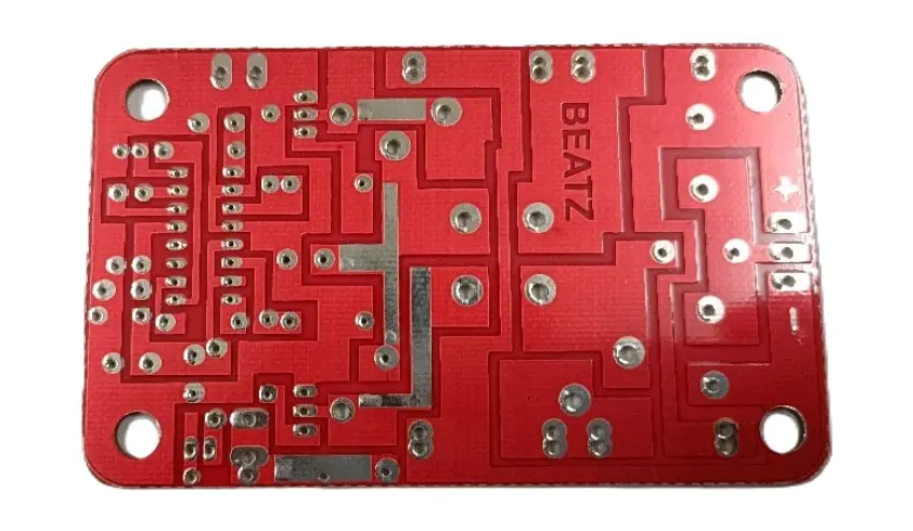
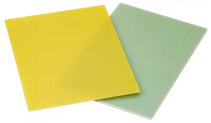
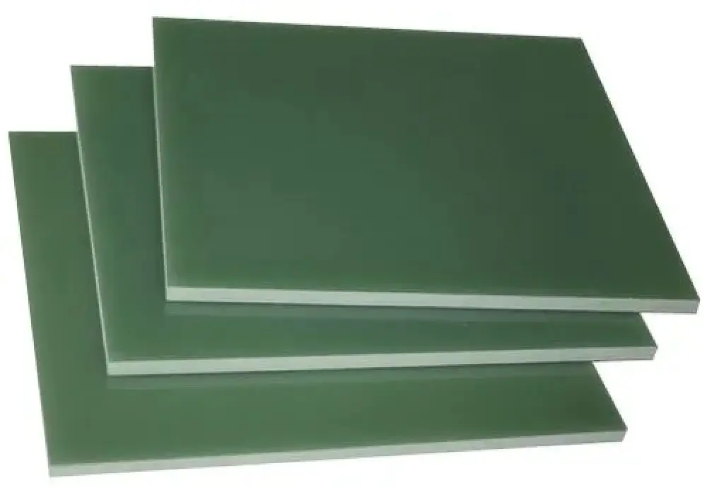
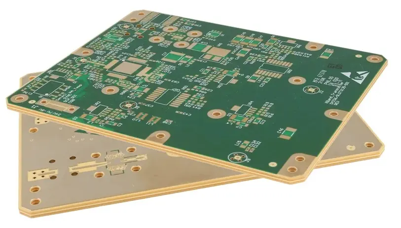
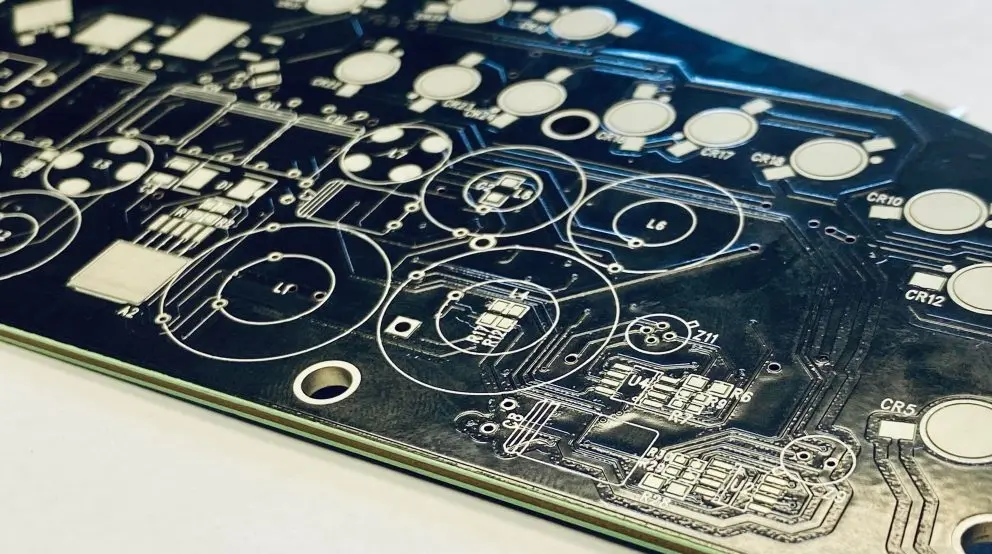
2.3 FR-4 (Glass Epoxy Laminate)
Composition:
- Woven fiberglass cloth impregnated with epoxy resin.
- The most widely used PCB base material.
Properties:
- Dielectric constant (Dk): 4.2–4.8
- Dissipation factor (Df): 0.02
- Tg: 130°C–180°C
- Excellent mechanical strength, insulation, and thermal stability.
- Compatible with multi-layer PCBs.
Advantages:
- Excellent electrical insulation and mechanical durability.
- High temperature and moisture resistance.
- Suitable for SMT (Surface Mount Technology) and high-speed circuits.
- Cost-effective and widely supported by manufacturers.
Disadvantages:
- Not ideal for high-frequency (>2 GHz) applications.
- Limited thermal conductivity (0.3 W/mK).
Applications:
- Computers and peripherals
- Industrial control systems
- Automotive electronics
- Consumer electronics
- Communication devices
2.4 CEM-1 and CEM-3 (Composite Epoxy Materials)
Composition:
- CEM-1: Paper core with epoxy resin and glass fabric surface.
- CEM-3: Woven glass cloth core with epoxy resin (similar to FR-4 but more economical).
Properties:
- Tg ≈ 125°C–150°C
- Good electrical insulation and mechanical strength.
- CEM-3 has smoother surfaces than FR-4, ideal for fine traces.
Advantages:
- CEM-1: Low-cost alternative to FR-4.
- CEM-3: Comparable electrical performance to FR-4 at reduced cost.
- Easier punching and drilling than FR-4.
Disadvantages:
- Lower mechanical strength than FR-4.
- Not recommended for multilayer PCBs (CEM-1).
- Slightly lower Tg than FR-4.
Applications:
- Power supplies
- LED lighting
- Consumer electronics
- Low-cost computing devices
2.5 PTFE (Teflon) Laminates
Composition:
- Made from Polytetrafluoroethylene (PTFE), a fluoropolymer with excellent dielectric properties.
Properties:
- Dk: 2.1–2.6
- Df: <0.001
- Tg: >260°C
- Excellent high-frequency performance and chemical resistance.
Advantages:
- Extremely low signal loss.
- Stable electrical characteristics over temperature and frequency.
- Resistant to moisture and chemicals.
Disadvantages:
- Expensive compared to FR-4.
- Difficult to machine and requires special processing.
- Poor dimensional stability without reinforcement.
Applications:
- RF and microwave circuits
- Radar systems
- Satellite communication
- High-speed data transmission equipment
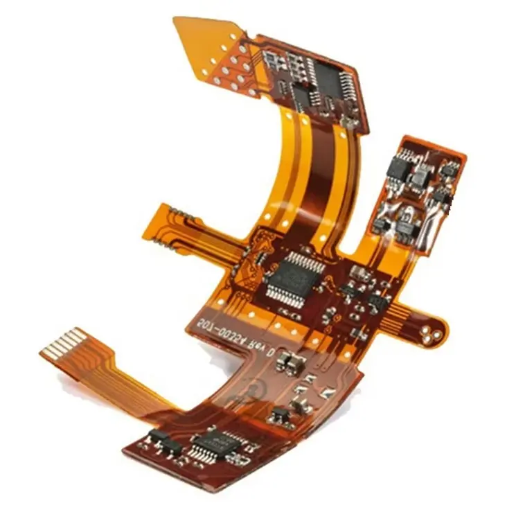
2.6 Polyimide PCB Material
Composition:
- Made from polyimide resin, a high-temperature polymer.
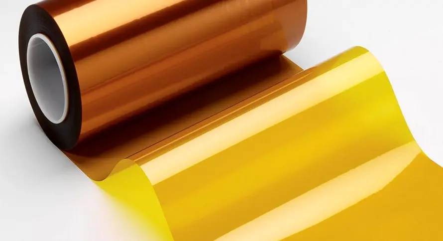
Properties:
- Tg ≈ 250°C
- Dk: 3.5–4.2
- Excellent thermal stability, flexibility, and chemical resistance.
Advantages:
- High operating temperature range (up to 260°C).
- Excellent for flexible and rigid-flex PCBs.
- Superior resistance to mechanical stress.
Disadvantages:
- High cost of material and processing.
- Slightly higher moisture absorption than FR-4.
Applications:
- Aerospace and military electronics
- Automotive engine control systems
- Flexible displays and wearables
- High-reliability industrial systems
2.7 Metal-Core PCB (MCPCB)
Composition:
- Base made of aluminum or copper, dielectric layer, and copper trace layer.
Properties:
- High thermal conductivity (1–3 W/mK).
- Excellent heat dissipation.
- Mechanically strong and dimensionally stable.
Advantages:
- Ideal for high-power LEDs and power converters.
- Superior heat management.
- Reduced thermal expansion compared to FR-4.
Disadvantages:
- Difficult to fabricate multilayer designs.
- Higher weight.
- Costlier than standard FR-4 boards.
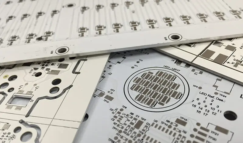
Applications:
- LED lighting
- Power amplifiers
- Motor controllers
- Power supply units
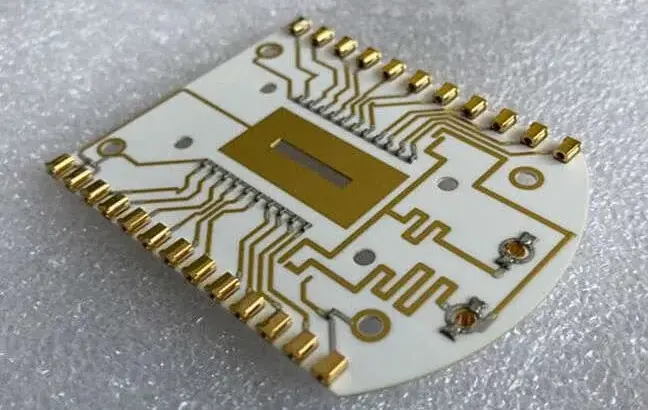
2.8 Ceramic PCB Material
Composition:
- Made from alumina (Al₂O₃), aluminum nitride (AlN), or beryllium oxide (BeO).
Properties:
- Dk: 6–10 (depending on ceramic type)
- Thermal conductivity: up to 200 W/mK (for AlN)
- Excellent high-frequency stability and heat dissipation.
| Material | Thermal Conductivity (W/mK) | Dielectric Constant | Max Temp (°C) |
|---|---|---|---|
| Alumina | 24 | 9.8 | 350 |
| Aluminum Nitride | 170 | 8.5 | 400 |
| Beryllium Oxide | 250 | 6.5 | 450 |
Advantages:
- Outstanding thermal performance.
- Excellent chemical and mechanical durability.
- Ideal for high-frequency, high-temperature, and harsh environment applications.
Disadvantages:
- Very expensive manufacturing process.
- Brittle and requires special handling.
Applications:
- Aerospace and military equipment
- Power electronics and lasers
- High-frequency RF and microwave modules
- Automotive sensors
3. Comparison Table of Common PCB Materials
| Material | Dielectric Constant (Dk) | Tg (°C) | Thermal Conductivity (W/mK) | Frequency Range | Cost | Common Applications |
|---|---|---|---|---|---|---|
| FR-1/FR-2 | 4.8–5.0 | 105–130 | 0.2 | Low | Very Low | Toys, power supplies |
| FR-4 | 4.2–4.8 | 130–180 | 0.3 | Medium | Medium | Computers, industrial |
| CEM-1/CEM-3 | 4.5 | 125–150 | 0.25 | Medium | Low | LED boards, appliances |
| Polyimide | 3.5–4.2 | 250 | 0.3 | High | High | Aerospace, flex PCBs |
| PTFE | 2.1–2.6 | 260 | 0.25 | Very High | Very High | RF, microwave, radar |
| MCPCB | 4–6 | 100–140 | 1–3 | Medium | Medium-High | Power LED, amplifiers |
| Ceramic | 6–10 | >300 | 24–200 | Very High | Very High | Power and RF systems |
Some Advance and New Types PCB materials
| Material | Specialty | Key Use |
|---|---|---|
| Rogers RO4000 / RO3000 series | Low Dk (~3.4), very low loss | RF, microwave, satellite |
| Nelco 4000-13 series | High Tg epoxy-glass | High-speed digital |
| Isola IS680 / Tachyon series | Ultra-low loss laminate | 5G and data centers |
| BT Epoxy (Bismaleimide Triazine) | Better moisture & heat resistance | High-end multilayer PCBs |
| Hybrid PCB (FR-4 + PTFE layers) | Mixed dielectric layers | Mixed-signal boards |
4. How to Choose the Right PCB Material
Selection depends on several design parameters:
| Factor | Recommended Material |
|---|---|
| Low-Cost Consumer Products | FR-1, FR-2, CEM-1 |
| General Purpose / Industrial | FR-4 |
| High-Temperature / Flexible Circuits | Polyimide |
| RF / Microwave Applications | PTFE, Ceramic |
| High-Power / LED Lighting | MCPCB |
| High Reliability Systems | FR-4 High-Tg, Polyimide, Ceramic |
Conclusion
The choice of PCB material plays a vital role in defining the performance, cost, and reliability of electronic systems.
- FR-4 remains the most commonly used material for general-purpose applications.
- PTFE and Ceramic dominate high-frequency and RF designs.
- Metal-core boards are preferred for high-power applications requiring efficient heat dissipation.
- Polyimide and flexible substrates serve in space-constrained and high-temperature environments.
Selecting the appropriate PCB material ensures optimal signal integrity, mechanical stability, and thermal management, making it one of the most critical steps in PCB design and manufacturing.
High Speed PCB Design: Essential Wiring Techniques for Optimal Performance
Revolutionary Axial Flux Printed Circuit Board (PCB) Stator Motor
