Understanding inductive reactance (XL) and capacitive reactance (XC) is essential for analyzing AC circuits, designing filters, oscillators, power electronics systems, and communication circuits.
This article explains all fundamental concepts including resistance, reactance, impedance, frequency response, graphs, ideal and real component behavior, solved examples, advantages, disadvantages, and applications.
In electronic circuits, especially those operating with alternating current (AC), components do not behave the same way as they do in direct current (DC) circuits. While resistors oppose current through resistance, inductors and capacitors oppose AC current through a phenomenon known as reactance. Reactance depends on the frequency of the applied signal and the physical properties of the component.
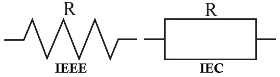
Resistance in Electrical Circuits
Resistance is the fundamental property of a material that opposes the flow of electric current.
Ohm’s Law
V = IR
Where:
- V = Voltage (Volts)
- I = Current (Amperes)
- R = Resistance (Ohms)
Key Characteristics of Resistance
- Independent of frequency.
- Dissipates energy in the form of heat.
- Same behavior in AC and DC circuits.
Power Dissipation
P = I²R
Resistors convert electrical energy into heat, unlike inductors and capacitors which mainly store energy.
Reactance
Reactance is the opposition to AC current caused by inductors and capacitors.
Unlike resistance, reactance:
- Depends on frequency
- Does not dissipate energy
- Stores energy in magnetic or electric fields
- It is measured in Ohms (Ω).
- Two types exist:
- Inductive Reactance (XL)
- Capacitive Reactance (XC)
Impedance
In AC circuits, the total opposition to current is called impedance (Z).
Impedance combines:
- Resistance (R)
- Reactance (X)
Z = R + jX
Where:
- Z = Impedance
- R = Resistance
- X = Reactance
- j = imaginary operator (phase shift)
Magnitude of impedance:
Z = √(R² + X²)
Impedance determines both magnitude and phase relationship between voltage and current.
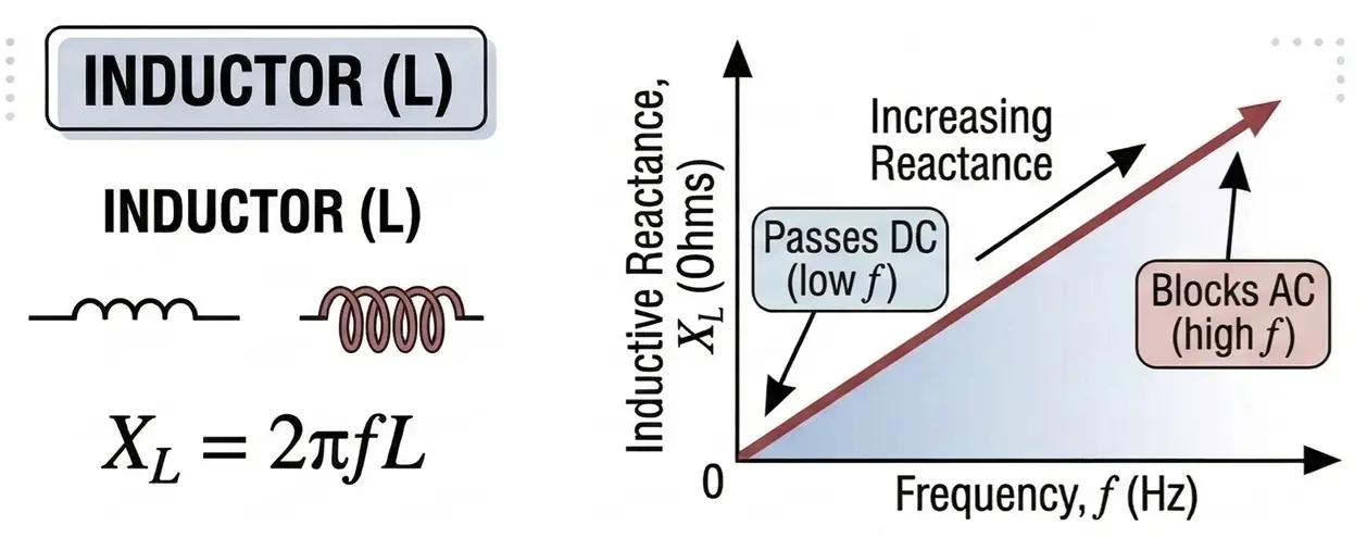
Inductive Reactance (XL)
Inductive reactance is the opposition to AC current offered by an inductor.
When current flows through an inductor, a magnetic field forms. Changes in current produce a voltage that opposes the change, according to Faraday’s law.
Formula
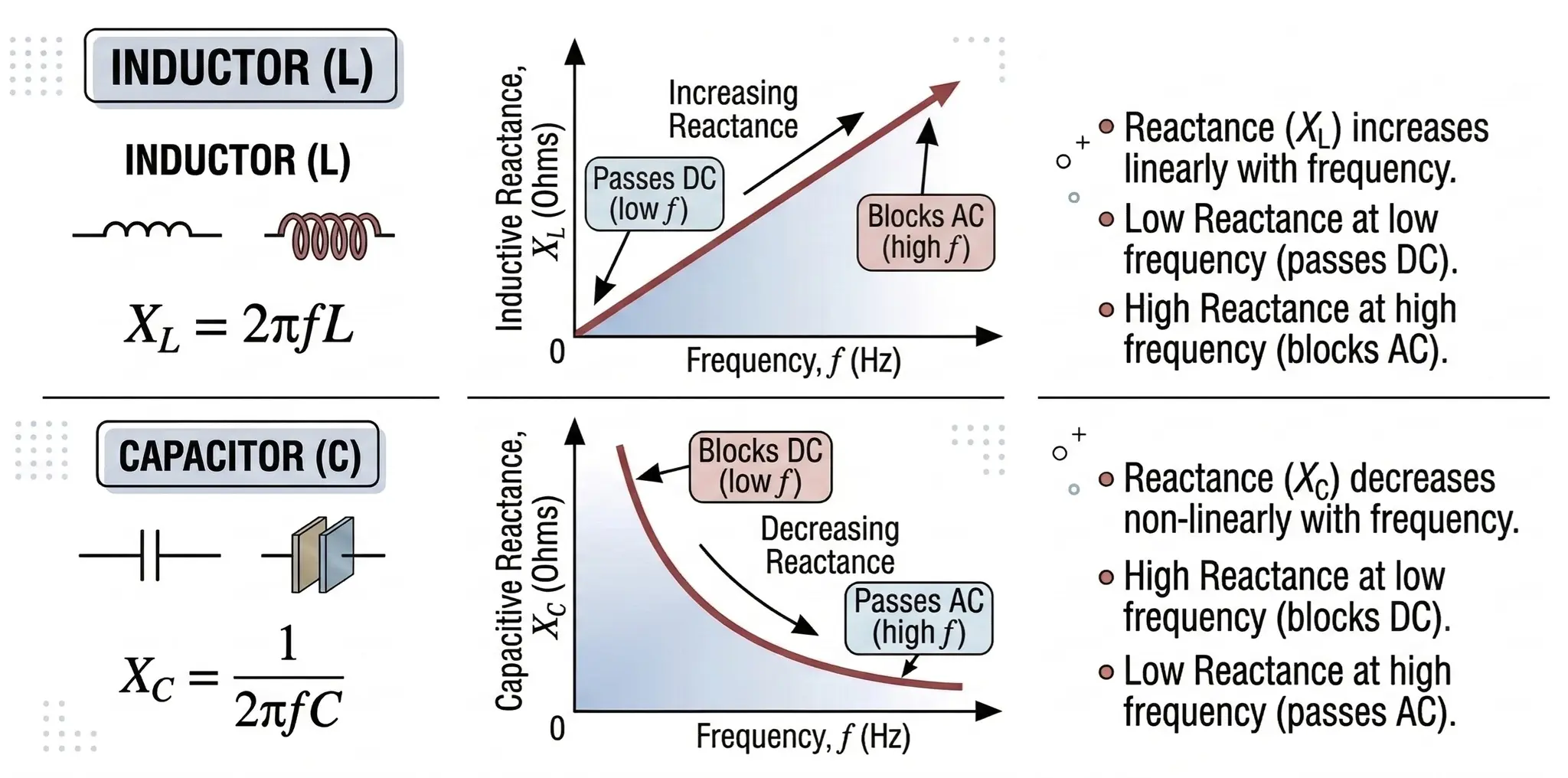
XL = 2πfL
Where:
- XL = Inductive reactance (Ω)
- f = Frequency (Hz)
- L = Inductance (Henries)
Key Observations
- XL increases with frequency
- XL increases with inductance
- At DC (f = 0) → XL = 0
Thus, an inductor behaves like a short circuit at DC.
Frequency Response of Inductive Reactance
If frequency increases, inductive reactance increases linearly.
Graph characteristics:
- X-axis → Frequency
- Y-axis → Reactance
- Straight line starting from origin
- Behavior
- Low frequency → small reactance
- High frequency → large reactance
This property makes inductors useful for high-frequency filtering.
Ideal Inductor Behavior
In an ideal inductor:
- No resistance
- No energy loss
- Perfect magnetic coupling
Voltage-current relationship:
V = L(dI/dt)
Energy stored:
E = ½LI²
Phase relationship:
Current lags voltage by 90°.
Real Inductor Behavior
In practice, inductors have several imperfections.
- Internal Resistance: Copper winding causes series resistance.
- Core Losses:
- Hysteresis loss
- Eddy current loss
- Parasitic Capacitance: Turns the coil into small capacitors.
- Equivalent circuit includes:
- Inductor
- Series resistance
- Parallel capacitance
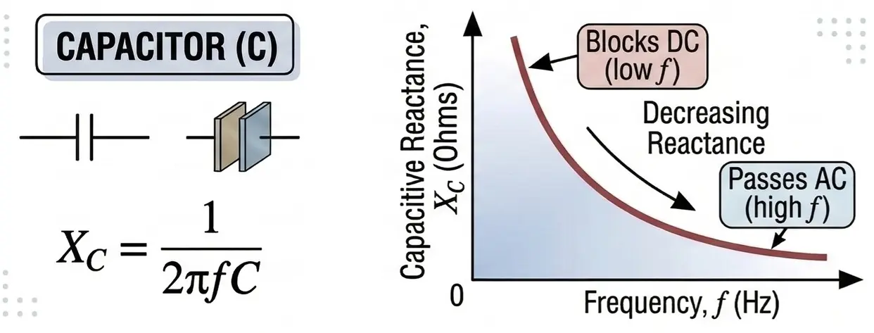
Capacitive Reactance (XC)
Capacitive reactance is the opposition to AC current offered by a capacitor.
Capacitors store energy in an electric field between two plates.
Formula
XC = 1 / (2πfC)
Where:
- XC = Capacitive reactance (Ω)
- f = Frequency (Hz)
- C = Capacitance (Farads)
Key Observations
- XC decreases with frequency
- XC decreases with capacitance
- At DC (f = 0) → XC = infinite
Therefore, capacitors behave like open circuits in DC.
Frequency Response of Capacitive Reactance
The graph shows an inverse relationship.
Graph characteristics:
- X-axis → Frequency
- Y-axis → Reactance
- Behavior:
- Low frequency → high reactance
- High frequency → low reactance
Thus, capacitors pass high frequencies easily.
Ideal Capacitor Behavior
In an ideal capacitor:
- No leakage current
- No resistance
- No energy loss
Current relationship:
I = C(dV/dt)
Energy stored:
E = ½CV²
Phase relationship:
Current leads voltage by 90°.
Real Capacitor Behavior
Practical capacitors contain several imperfections.
- Equivalent Series Resistance (ESR): Internal resistance produces power loss.
- Leakage Resistance: Dielectric allows small current leakage.
- Equivalent Series Inductance (ESL): Leads and plates introduce inductance.
- Equivalent model contains:
- Capacitor
- Series resistance
- Leakage resistance
- Small inductance
These parasitic effects affect high-frequency performance.
Phase Relationships in AC Circuits
- Inductor:
- Voltage leads current by 90°
- Capacitor:
- Current leads voltage by 90°
- This phase shift plays a critical role in:
- Resonance circuits
- AC power systems
- Signal filtering
Reactance Phasor Diagrams
Phasor diagrams are graphical representations used in AC circuit analysis to illustrate the phase relationship between voltage and current. In reactance-based components such as inductors and capacitors, voltage and current are not in phase. Instead, they are separated by a 90° phase shift.
Phasor diagrams simplify AC circuit analysis by representing sinusoidal quantities as rotating vectors (phasors) in the complex plane.
Phasor Diagram of a Pure Inductor
In a purely inductive circuit:
- Voltage leads current by 90°
- Current lags voltage by 90°
This occurs because an inductor resists changes in current due to the magnetic field created
around the coil.

Mathematically:
V = L (dI/dt)
If the current waveform is sinusoidal:
I = Im sin(ωt - π/2)
Then voltage becomes:
V = Vm sin(ωt)
Since cosine leads sine by 90°, the voltage waveform leads current.
Key Observations
- Current lags voltage
- Power consumed is ideally zero
- Energy is stored temporarily in the magnetic field
Phasor Diagram of a Pure Capacitor
In a purely capacitive circuit:
- Current leads voltage by 90°
- Voltage lags current by 90°

The relationship comes from:
I = C (dV/dt)
If voltage is sinusoidal:
V = Vm sin(ωt)
Then current becomes:
I = Vm sin(ωt + π/2)
Thus, current leads voltage by 90°
Key Observations
- Current leads voltage
- Energy is stored in the electric field
- No real power dissipation in an ideal capacitor
Reactance vs Frequency
Reactance varies significantly with frequency. The following tables illustrate how inductive and capacitive reactance change as frequency increases.
Inductive Reactance Example
For L = 10 mH
XL = 2πfL
| Frequency | XL |
|---|---|
| 50 Hz | 3.14 Ω |
| 100 Hz | 6.28 Ω |
| 1 kHz | 62.8 Ω |
| 10 kHz | 628 Ω |
| 100 kHz | 6280 Ω |
Capacitive Reactance Example
For C = 1 µF
XC = 1 / (2πfC)
| Frequency | XC |
|---|---|
| 50 Hz | 3183 Ω |
| 100 Hz | 1591 Ω |
| 1 kHz | 159 Ω |
| 10 kHz | 15.9 Ω |
| 100 kHz | 1.59 Ω |
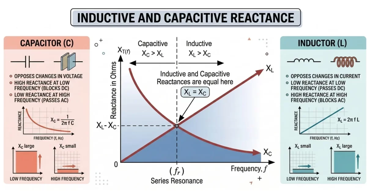
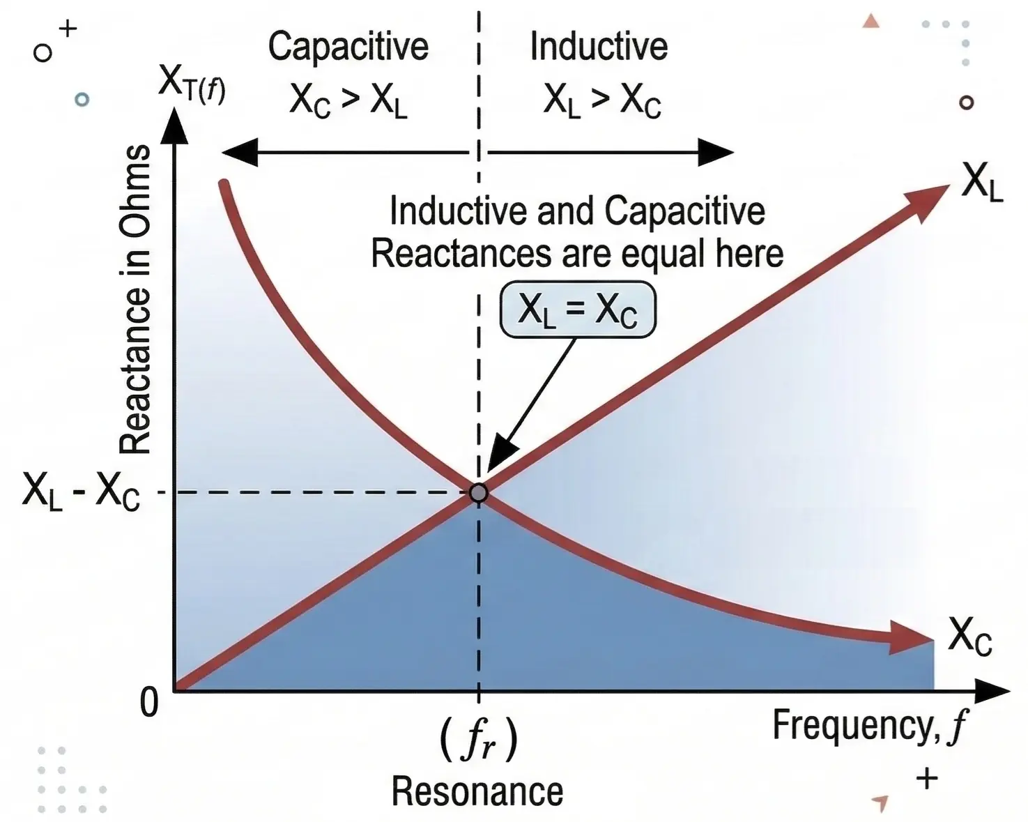
Frequency Response and Resonance
When inductors and capacitors are combined, resonance occurs.
Resonant frequency:
fr = 1 / (2π√LC)
At resonance:
XL = XC
Total reactance becomes zero and circuit behaves purely resistive.
Resonance is used in:
- Tuned radio circuits
- Oscillators
- RF communication systems
Practical Circuit Examples (RL, RC, RLC)
Reactance is widely used in real electronic circuits to control
frequency response and signal behavior.
RL Circuit Example
An RL circuit contains:
- Resistor (R)
- Inductor (L)
Total impedance:
Z = √(R² + XL²)
Applications
- Low-pass filters
- Current limiting circuits
- Motor drive circuits
RC Circuit Example
An RC circuit contains:
- Resistor (R)
- Capacitor (C)
Total impedance:
Z = √(R² + XC²)
RLC Circuit Example
An RLC circuit contains:
- Resistor (R)
- Inductor (L)
- Capacitor (C)
Impedance:
Z = √(R² + (XL − XC)²)
At resonance:
XL = XC
Thus:
Z = R
Solved Examples
Examples 1
Find inductive reactance of a 10 mH inductor at 1 kHz.
XL = 2πfL
XL = 2 × 3.14 × 1000 × 0.01
XL = 62.8 Ω
Example 2
Find capacitive reactance of 1 µF capacitor at 1 kHz.
XC = 1 / (2πfC)
XC = 1 / (2 × 3.14 × 1000 × 1×10⁻⁶)
XC = 159 Ω
Example 3
Calculate impedance of a circuit with: R = 10 Ω, XL = 30 Ω
Z = √(R² + XL²)
Z = √(10² + 30²)
Z = √(100 + 900)
Z = 31.6 Ω
Advantages of Reactance in Circuits
- Frequency Control
- Allows circuits to respond differently at different frequencies.
- Signal Filtering
- Energy Storage
- Inductors and capacitors temporarily store electrical energy.
- Resonant Circuit Design
- Essential for designing resonant circuits used in radio receivers and transmitters.
- Power Factor Correction
- Capacitors compensate for inductive loads to improve power factor.
Disadvantages of Reactance
- Frequency Sensitivity
- Reactance varies with frequency, making circuit behavior frequency dependent.
- Component Losses
- Practical inductors and capacitors have internal resistance and losses.
- Large Size of Inductors
- High inductance values require bulky coils.
- Parasitic Effects
- Stray capacitance and inductance can distort circuit performance at high frequencies.
Applications of Reactance
- Filters
- RC, RL, and LC filters remove unwanted frequency components.
- Oscillators
- LC circuits generate stable oscillations.
- Power Supplies
- Capacitors smooth rectified voltage in power supply circuits.
- RF Circuits
- Reactance is used for tuning radio frequency signals.
- Signal Coupling
- Capacitors block DC while allowing AC signals to pass.
- Transformers and Inductors
- Used in switching power supplies and power converters.
- Impedance Matching
- Ensures maximum power transfer in RF systems.
Comparison of Inductive and Capacitive Reactance
| Property | Inductive Reactance | Capacitive Reactance |
|---|---|---|
| Formula | XL = 2πfL | XC = 1/(2πfC) |
| Frequency effect | Increases with frequency | Decreases with frequency |
| Phase | Current lags voltage | Current leads voltage |
| DC behavior | Short circuit | Open circuit |
| Energy storage | Magnetic field | Electric field |
Summary
Inductive reactance and capacitive reactance are fundamental properties of AC circuits. While resistance opposes current independent of frequency, reactance varies with frequency and arises from energy storage in magnetic or electric fields.
Inductors oppose high frequencies while capacitors oppose low frequencies, allowing engineers to design circuits that selectively pass or block signals. These properties form the basis of filters, oscillators, power electronics, RF communication systems, and many modern electronic devices.
Understanding these principles enables the design and analysis of complex AC circuits with predictable and reliable performance.
Types of Filter Circuits: Working Principles, Formula & Applications
RC Filters: Circuit Diagram, Types, Working and Applications
RL Filters: Circuit Diagram, Working, Types, and Applications
Different Types of Oscillators with Working and Applications
