Hello friends,
Do you know how to switch between two power supplies or current sources using a Current Switching Circuit using Arduino and Relays? Welcome to another interesting article, suppose you want to operate a device that can be operated based on the room temperature or a temperature inside the device, let’s understand this with a real example suppose you want to operate a Peltier based on the room temperature, you want to regulate its temperature. At the end of this article, you find yourself ready to design of current switching circuit using Arduino.
Peltier – A device that operates on a heavy current, the cooling effect is directly proportional to the supply of a current. If more current is supplied the cooling effect will be more, and if less current will be supplied then the cooling effect will be less. For example, if the room temperature ranges between 20 ℃ to 25 ℃ then we need to supply more current in order to reduce room temperature, and if the room temperature ranges between 15 ℃ to 20 ℃ then we need to supply less current. In the above example instead of Peltier, you can connect any load which you want to control based on the feedback from the temperature sensor. And Arduino will take care to operate the device according to your defined conditions. With the help of the circuit attached in this article, you can switch between two current sources or two voltage sources.
This is a very easy and simple circuit to perform and execute, you will able to achieve the entire functioning of the circuit and understand it, just make sure that you will read the whole article till the end.
Let’s check what are components required
- 10k 103 NTC thermistor,
- 10k ohm Resistor
- Arduino
- Relay (as per your operating parameters)
- BJT (Bipolar Junction Transistor)
- Diode
- Current sources of desire range or voltages sources of desire range
- A load of your choice (Air conditioners, Refrigerator, Peltier, etc.)
Thermistor-:
Thermistors are electronic components whose resistance varies with changes in the surrounding temperature there are two types of thermistors first one is a PTC thermistor, and the second one is an NTC thermistor.
PTC Thermistors – Stand for Positive Temperature Coefficient (PTC), in this type of thermistor the resistance is directly proportional to the temperature if the temperature rises then the resistance of the thermistor also increases, and if the temperature decreases the resistance of the thermistor is also decreases.
NTC Thermistor – Stand for Negative Temperature Coefficient (NTC) in this type of thermistor the resistance inversely proportional to the temperature for example if the temperature of the thermistor increases then the resistance of the thermistor decreases and vice versa.
In our circuit diagram, we have used a 103 NTC type thermistor whose internal resistance is 10k ohms and whose resistance inversely varies with respect to changes in the surrounding temperature. So based on the temperature sensed by the thermistor we will put conditions to switch between two power supplies or current sources.
To make it simpler let’s divide the entire circuit diagram into two parts, in the first part we will interface the NTC thermistor and print the output of the sensed temperature. And in the second part will interfere with the load circuitry with Arduino. In the final step, we merge both outputs to see the final output.
Circuit Diagram-:
Interfacing 103 NTC thermistor with Arduino-:
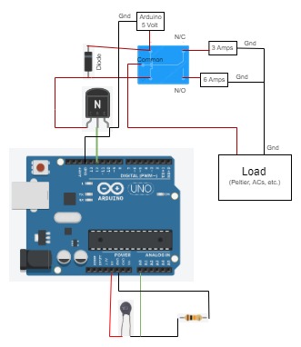
Make the connection of the NTC thermistor with Arduino as shown in the above circuit diagram. In our case, a 10k NTC-type thermistor is used. With an NTC of 10k, this thermistor has a resistance of 10k at 25°C. The voltage across the 10k resistor is fed into the ADC on the UNO board. The thermistor resistance is calculated using a straightforward voltage divider network formula.
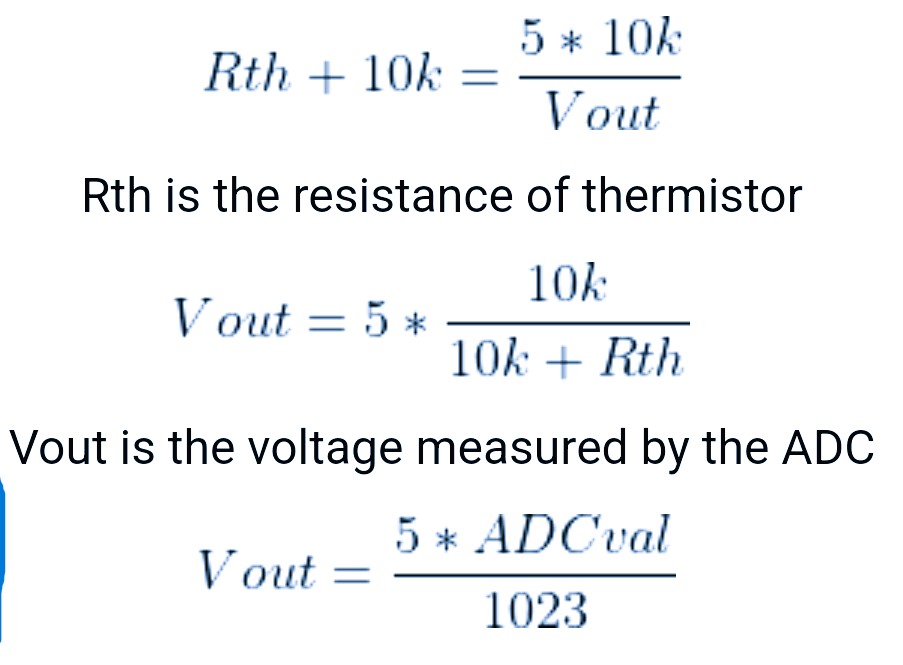
Steinhart-Hart equation can be used to calculate the temperature from thermistor resistance.
Steinhart-Hart equation ==> Temperature = 1 / (A + B[ln(R)] + C[ln(R)]^3) Kelvin
where A = 0.001129148, B = 0.000234125, and C = 8.76741*10^(-8).
R represents the thermistor resistance.
In the code section, you will get more understanding of the calculation of the temperature.
Interfacing of Load Circuitry with Arduino-:
Connect the BJT, relay, load, diode, voltage, or current sources as shown in the above circuit diagram.
The Relay Coil Terminals-:
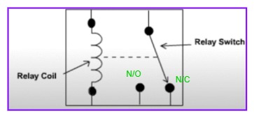
The above figure named “relay terminals” are showing the 5 terminals of the relay model JQC-3FC(T73DC06V). in this project, we have used the same relay, the relay switch (common) terminal has directly connected to the load and at the N/O & N/C terminal we have connected two different power supplies. A 5v from the Arduino is connected d the coil terminal to trigger the coil and to perform switching action between N/O and N/C.
Operation With Arduino
Let’s understand some logical parts to safeguard Arduino from voltage spikes & for a smooth operation of the above circuit. If you observe the circuit, pin 12 is the output pin for the Arduino, based on the programmed conditions it will provide high or low voltage to activate the relay coil, but in practice, it has insufficient current to activate the relay coil, so We have connected BJT in the circuit.
Pin 12 of the Arduino is connected at the base of the BJT now BJT will act as a switch. Based on the output of Arduino pin 12, BJT will switch between an on/off state. A diode is connected to avoid reverse flow or voltage spikes, otherwise, Arduino may get damaged due to reverse voltage spikes. One terminal of the relay coil is connected to the 5v of the Arduino.
Arduino Code
const int thermistorPin = A0; // Thermistor connected to A0
const int relayPin = 12; // Relay control via BJT connected to D12

// Constants for thermistor calculation
const float seriesResistor = 10000.0; // 10k resistor
const float nominalResistance = 10000.0; // Resistance at 25°C
const float nominalTemperature = 25.0; // in Celsius
const float bCoefficient = 3950.0; // B value of thermistor

const int adcMax = 1023;

// Temperature threshold
const float thresholdTemp = 30.0; // Set your desired threshold here

void setup() {
pinMode(relayPin, OUTPUT);
digitalWrite(relayPin, LOW); // Relay off by default
Serial.begin(9600);
}

void loop() {
int adcValue = analogRead(thermistorPin);

// Convert ADC to resistance
float resistance = seriesResistor / ((adcMax / (float)adcValue) - 1.0);

// Convert resistance to temperature (Steinhart-Hart approximation)
float temperature;
temperature = resistance / nominalResistance; // (R/Ro)
temperature = log(temperature); // ln(R/Ro)
temperature /= bCoefficient; // 1/B * ln(R/Ro)
temperature += 1.0 / (nominalTemperature + 273.15); // + (1/To)
temperature = 1.0 / temperature; // Invert
temperature -= 273.15; // Convert to Celsius

// Debug
Serial.print("Temp: ");
Serial.print(temperature);
Serial.println(" C");

// Relay control
if (temperature > thresholdTemp) {
digitalWrite(relayPin, HIGH); // Turn relay ON
} else {
digitalWrite(relayPin, LOW); // Turn relay OFF
}

delay(1000); // Wait a bit before next reading
}
Based on your requirement connect voltage or current sources at the N/C (normally closed) and N/O (normally open) terminals of the relay and the load device should be connected to the common terminal of the relay. For the connection refer to the circuit diagram.
Happy Learning………………………. check out our articles on the counter circuit.

IC CD4029, IC 74163, IC 74160, IC 7493, IC 74193, IC 7490, Counter Circuit using 555 timers.
IOT Based Air Quality Monitoring System with ESP32 & BME680 Sensor
Arduino UNO R4 Wi-Fi / Minima Pinout, Specifications & Pricing

When using a microcontroller, for example, an AVR ATmega238p (Arduino UNO) you should display the code used in it as well.
I have updated the article
Thank You