Here are the basic electronics tutorial circuits for beginners. You can find here tutorials on operational amplifiers (opamp), transistor, MOSFETs, 555 timer IC, audio amplifiers and many more.
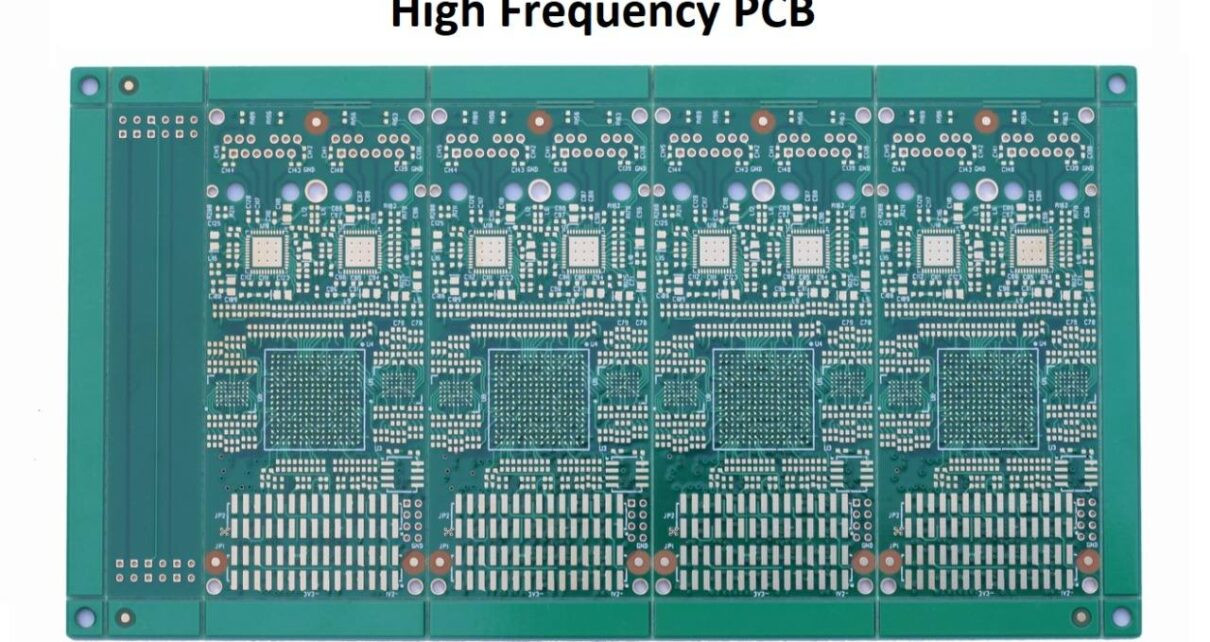
Here is everything you need to know about high frequency PCBs, including what high frequency PCB is, features, materials used, and benefits of high frequency PCB. Today, electronic devices are being developed with high frequency. Satellite devices and most information products move towards high frequency and high speed. Hence, more advanced PCBs are required, such […]
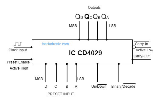
CD4029 is a Synchronous, Programmable, Presettable, 4 Bit Up/Down & Binary/Decade counter which is very much similar to the IC 74193, However, there is one notable change between IC74193 and CD4029: CD4029 has one unique pin that determines its counter configuration for Binary and BCD counter mode, allowing the IC to count similarly to binary […]
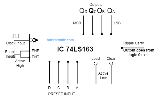
IC74163 Integrated Presettable Synchronous 4-bit Modulo-16 Up counter. The IC is a synchronous counter as all 4 flip-flops are integrated into the same chip & they receive the same clock pulse (clock signal). The IC74163 is a completely programmable binary counter due to its four preset inputs, which allow it to begin counting with any […]
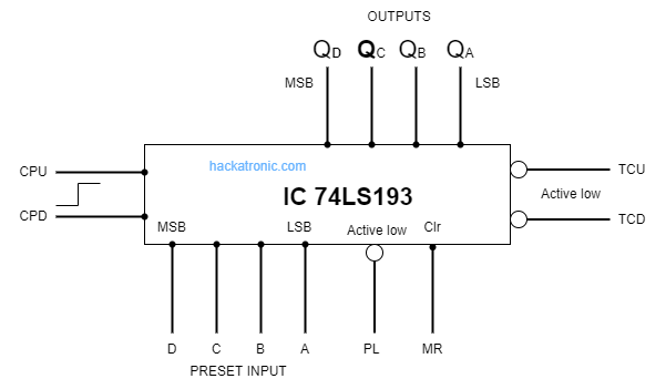
IC 74193 is a 4-bit presettable synchronous MODULO-16 Up/Down binary counter IC. IC74193 has two separate clock input pins to count up and count down, the output is synchronous with the clock inputs. The separate Terminal Count Up & Terminal Count Down are provided which is useful for designing higher counter or cascading the IC74193. The […]
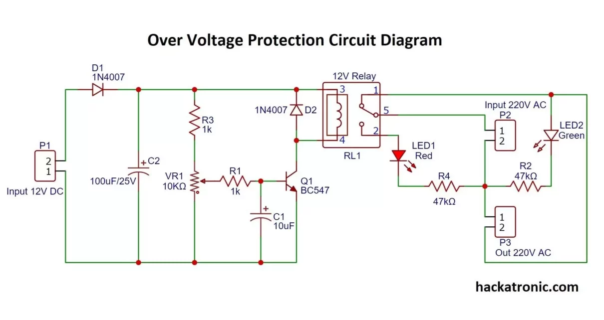
In this tutorial, you will learn how to make this over-voltage protection circuit. It requires fewer components and is very effective in overvoltage conditions. It will cost you around 3$ to 5$ depending on the quality of components. Overvoltage occurs when the voltage in a circuit is raised above its upper design limits. This condition […]
Controlling the brightness of an LED or blinking it continually by passing various delays with PWM (Pulse Width Modulation) it might be your first Raspberry Pi 4 learning experience. In this article, we perform three activities which are, Turning On & Off LED. Blinking it using PWM at different frequencies. Controlling the brightness of the […]