Since times immemorial the six-faced cube, ever since the man invented it, has always been of immense importance in all kinds of games.

Here is an electronic version of the dice which is just the very thing to accompany the modern electronic games. This digital dice is “cent percent impartial” in the sense that the “thrower” and the “type of throw” does not affect it. The circuit is based on CMOS ICs which add to its reliability and long battery life. The device is compact enough to be carried around in the pocket. The dice costs just so low that a second thought over making it wouldn’t be required.
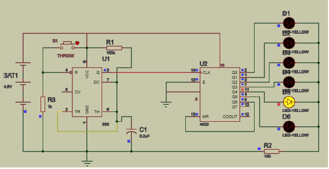
Circuit For Digital Dice Roller:
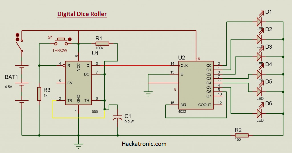
Working of the Digital dice roller circuit:
The circuit is based on CD4022 which is an 8-stage counter. Six outputs are required and therefore the counter is used in the divide-by-six mode, i.e., the chip counts up to six and resets on the seventh pulse. The clock pulses are provided by IC1 which is used in astable mode.
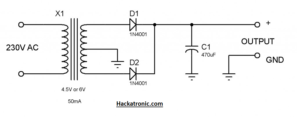
Although a PP3 battery is best suited for portable operation. If The AC mains operation is needed, then the power supply circuit given may be used. This unregulated supply would be more than sufficient.
Construction:
Construction is simple. Extreme care must be taken while soldering the ICs and other semiconductors.
60/40 type core along with a 10-watt iron must be used for soldering. The LEDs should be soldered at a height of say 10mm. The assembly can be housed in any cabinet with a transparent panel, or holes can be drilled. The LEDs and pushbuttons can be mounted on the front panel. The circuit can be connected to a battery and one LED should light up. The digital dice is now ready for a throw.
Components (Main Circuit)
Semiconductors
U1 NE555 timer
U2 HCF4022
D1-D6 LEDs, 5 mm, any color, preferably red
Resistors
R1 100k
R2 150R
R3 1k
Capacitors
C1 0.2uF (ceramic)
Miscellaneous
S1 push button
Cabinet
Solder etc
The battery BAT1 can be strong 3 cells in series. But the 4.5 or 6v power supply can be made easier to power up the circuit. For a portable issue, I will recommend using high quality 3 cells in series.
Circuit For Power Supply:
Components (Power Supply)
Semiconductors
D1, D2 1N4001
Capacitors
C1 470uF (10V)
Miscellaneous
X1 4.5V or 6 volts step down transformer
Also, You can use 5V from a battery.
L293D Pin Diagram, Working and Interfacing of L293D with Arduino