This article is on MOSFETs (Metal-Oxide-Semiconductor Field-Effect Transistor), covering the difference between D-MOSFET and E-MOSFETs with construction, working, advantages, disadvantages, and applications.
MOSFETs are the most common types of Field Effect Transistors (FETs) in Modern electronics. It functions as a voltage-controlled device and delivers high input impedance along with fast switching speed. MOSFETs are the backbone of analog and digital circuits — found in amplifiers, power supplies, microprocessors, and communication systems.
Types of MOSFETs
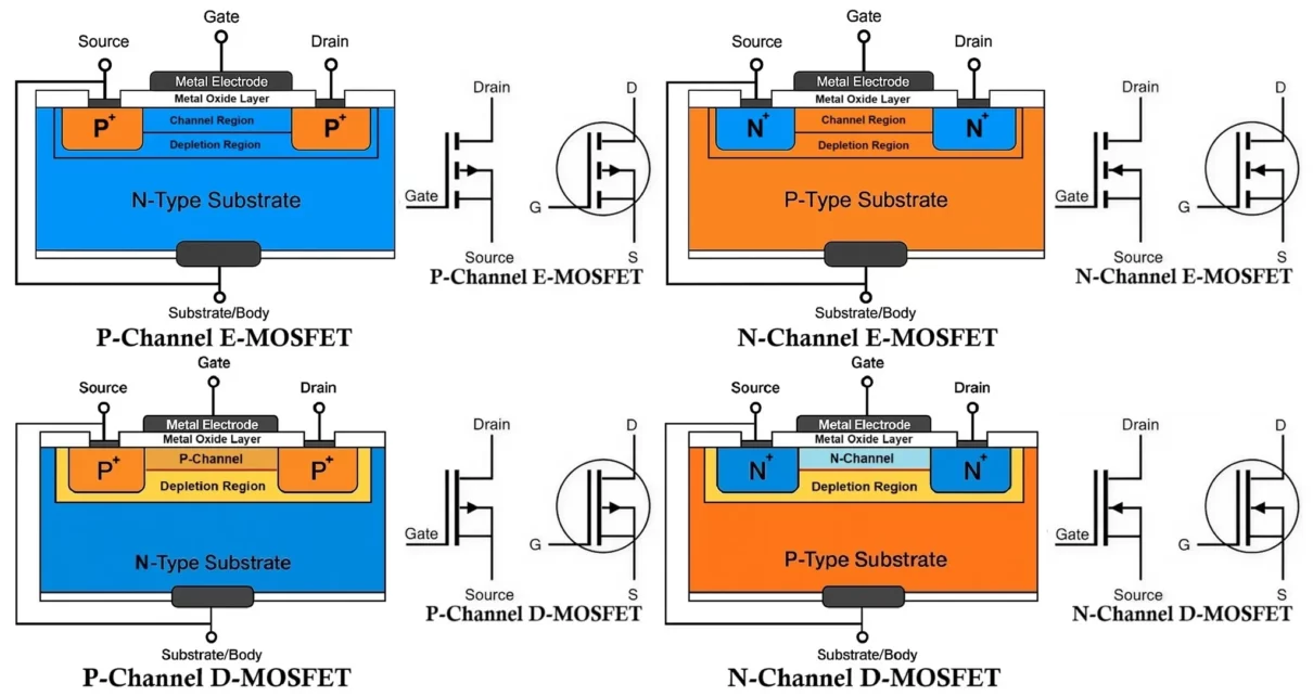
MOSFETs are mainly divided into two broad types, each further classified based on the channel type (N-channel or P-channel):
- Depletion-Type MOSFET (D-MOSFET)
- N-Channel D-MOSFET
- P-Channel D-MOSFET
Enhancement-Type MOSFET (E-MOSFET)
- N-Channel E-MOSFET
- P-Channel E-MOSFET
Depletion Type MOSFET (D-MOSFET):
A Depletion-type MOSFET (D-MOSFET) is a type of Metal-Oxide-Semiconductor Field Effect Transistor that is “normally ON” at zero gate-to-source voltage (VGS). This is because the channel forms during manufacturing, so current flows between the drain and source even without any external gate voltage. Because of this behavior, we also call D-MOSFETs “normally ON” transistors.
D-MOSFETs can operate in both depletion mode (reducing current) and enhancement mode (increasing current), offering greater flexibility compared to enhancement-only MOSFETs (E-MOSFETs).
Construction of D-MOSFET (Depletion Type MOSFET):
A D-MOSFET can be constructed as either an n-channel or p-channel device, depending on the type of doped semiconductor used to create the channel.
N-Channel D-MOSFET
- Substrate: Lightly doped p-type.
- Channel: n-type region diffused between source and drain; present at fabrication.
- Source & Drain: Heavily doped n+ regions at either end of the channel.
- Gate: A metal or polysilicon electrode placed above the channel, insulated by a thin SiO₂ (silicon dioxide) layer.
The channel contains electrons as majority carriers, and these electrons allow current flow when a voltage is applied between drain and source.
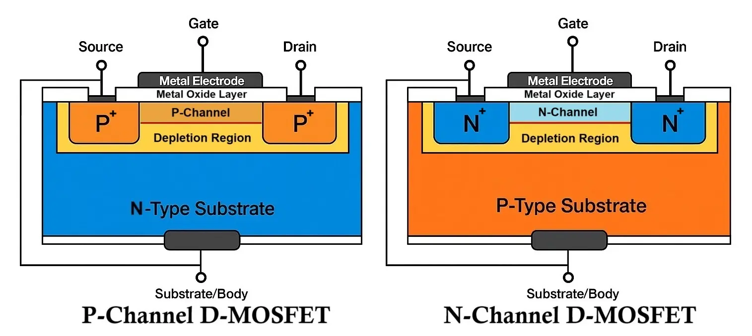
P-Channel D-MOSFET
- Substrate: Lightly doped n-type.
- Channel: p-type region between source and drain; present at fabrication.
- Source & Drain: Heavily doped p+ regions at either end of the channel.
- Gate: A metal or polysilicon electrode placed above the channel, insulated by a thin SiO₂ (silicon dioxide) layer.
The channel contains holes as majority carriers; they allow current to flow when a voltage is applied between drain and source.
Working of D-MOSFET (Depletion Type MOSFET):
The operation of a D-MOSFET depends on the gate-to-source voltage (VGS) and falls into two modes:
VGS = 0V (No Gate Bias – Normal ON State)
- Since the channel exists by default, current flows freely between drain and source when VDS is applied.
- The MOSFET is naturally conducting – this is why it is called a normally ON device.
Depletion Mode (VGS < 0 for N-Channel, > 0 for P-Channel)
- A reverse bias is applied to the gate.
- This creates an electric field that repels charge carriers from the channel.
- In n-channel, negative VGS repels electrons.
- In p-channel, positive VGS repels holes.
- As carriers are depleted, the channel narrows, and drain current (ID) decreases.
- When VGS reaches a critical value called threshold voltage (VTh), the channel becomes fully depleted and current stops.
At VGS = –VTh (for N-channel) or +VTh (for P-channel), the D-MOSFET switches OFF.
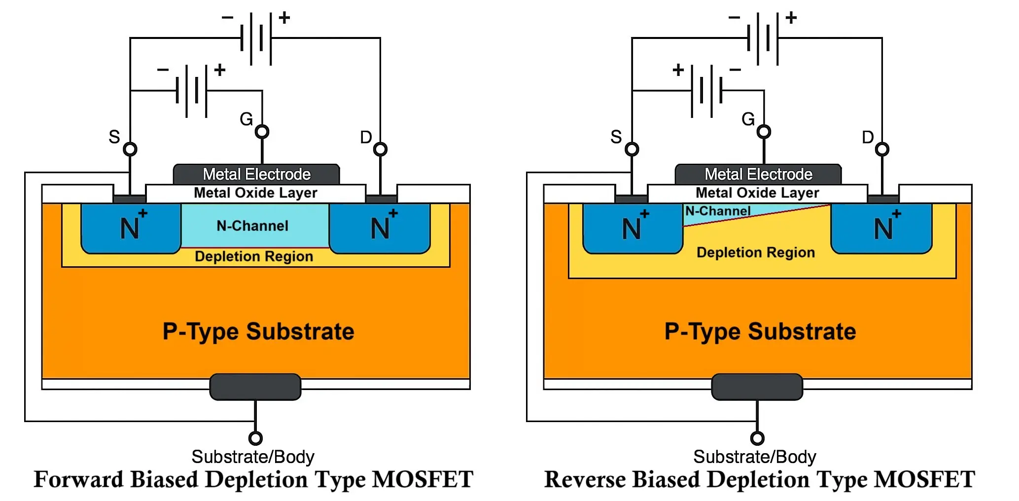
Enhancement Mode (VGS > 0 for N-Channel, < 0 for P-Channel)
- A forward bias is applied between gate and source.
- This attracts more majority carriers into the channel.
- In n-channel, positive VGS attracts electrons.
- In p-channel, negative VGS attracts holes.
- The channel width increases, increasing ID.
- This behavior is similar to enhancement-mode MOSFETs.
The ability to operate in both modes makes D-MOSFETs versatile in analog applications.
VI characteristics of MOSFET explained with diagrams.
Symbols of Depletion-Type MOSFETs
Symbols for D-MOSFETs are similar to those of E-MOSFETs but with a solid line representing the already-formed channel between source and drain.
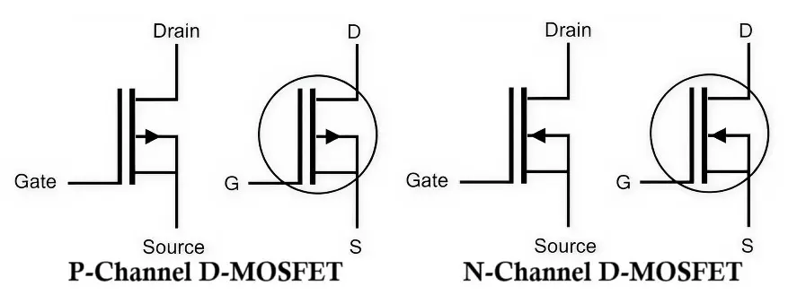
- Arrow direction indicates the type:
- Arrow in → N-channel
- Arrow out → P-channel
Comparison of N-Channel D-MOSFET and P-Channel D-MOSFET
| Parameter | N-Channel D-MOSFET | P-Channel D-MOSFET |
|---|---|---|
| Charge carriers | Electrons (majority) | Holes (majority) |
| Substrate type | P-type | N-type |
| Threshold voltage | Negative | Positive |
| Enhancement bias | Positive VGS | Negative VGS |
| Depletion bias | Negative VGS | Positive VGS |
- A Depletion-type MOSFET is a normally ON device with a pre-formed channel.
- It can operate in both depletion (reduce current) and enhancement (increase current) modes by varying VGS.
- N-channel D-MOSFETs use electrons and have a negative threshold voltage, while P-channel D-MOSFETs use holes and have a positive threshold voltage.
- The versatility of D-MOSFETs makes them ideal for various analog and signal processing applications.
Enhancement Type MOSFET (E-MOSFET):
An Enhancement-type MOSFET (E-MOSFET) is a type of MOSFET that is normally OFF when the gate-to-source voltage (VGS) is zero. Unlike D-MOSFETs, the channel is not pre-formed during manufacturing. Instead, the conducting channel is induced by applying a suitable gate voltage.
Because of this characteristic, E-MOSFETs are also known as normally OFF transistors.
E-MOSFETs operate only in enhancement mode, i.e., they require a gate voltage to create a channel and allow current flow between the drain and source. They are widely used in digital switching and power electronics due to their low leakage current and high efficiency.
Construction of E-MOSFET (Enhancement Type MOSFET):
E-MOSFETs are fabricated in n-channel and p-channel configurations.
N-Channel E-MOSFET
- Substrate: Lightly doped p-type semiconductor.
- Source & Drain: Heavily doped n+ regions diffused into the p-type substrate.
- Gate: A metal or polysilicon gate is deposited above the substrate.
- Insulating Layer: A thin layer of SiO₂ (silicon dioxide) insulates the gate from the substrate.
- No physical channel exists between source and drain initially.
The absence of a channel at VGS = 0V means no current flows until a positive gate voltage is applied.
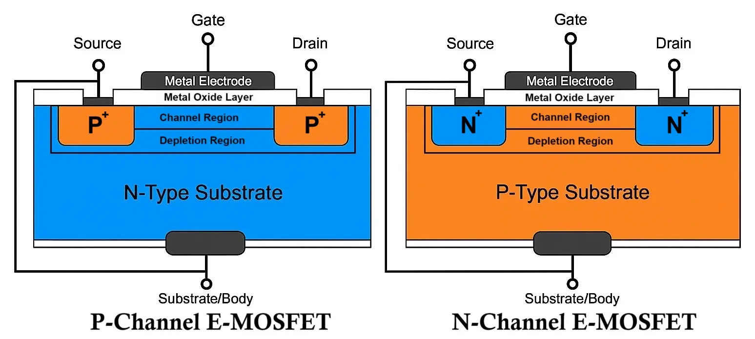
P-Channel E-MOSFET
- Substrate: Lightly doped n-type semiconductor.
- Source & Drain: Heavily doped p+ regions diffused into the substrate.
- Gate: A metal or polysilicon gate is present above the substrate.
- Insulating Layer: A thin layer of SiO₂ (silicon dioxide) insulates the gate from the substrate.
- No physical p-type channel exists at zero gate bias.
Requires a negative gate voltage to induce a p-type channel.
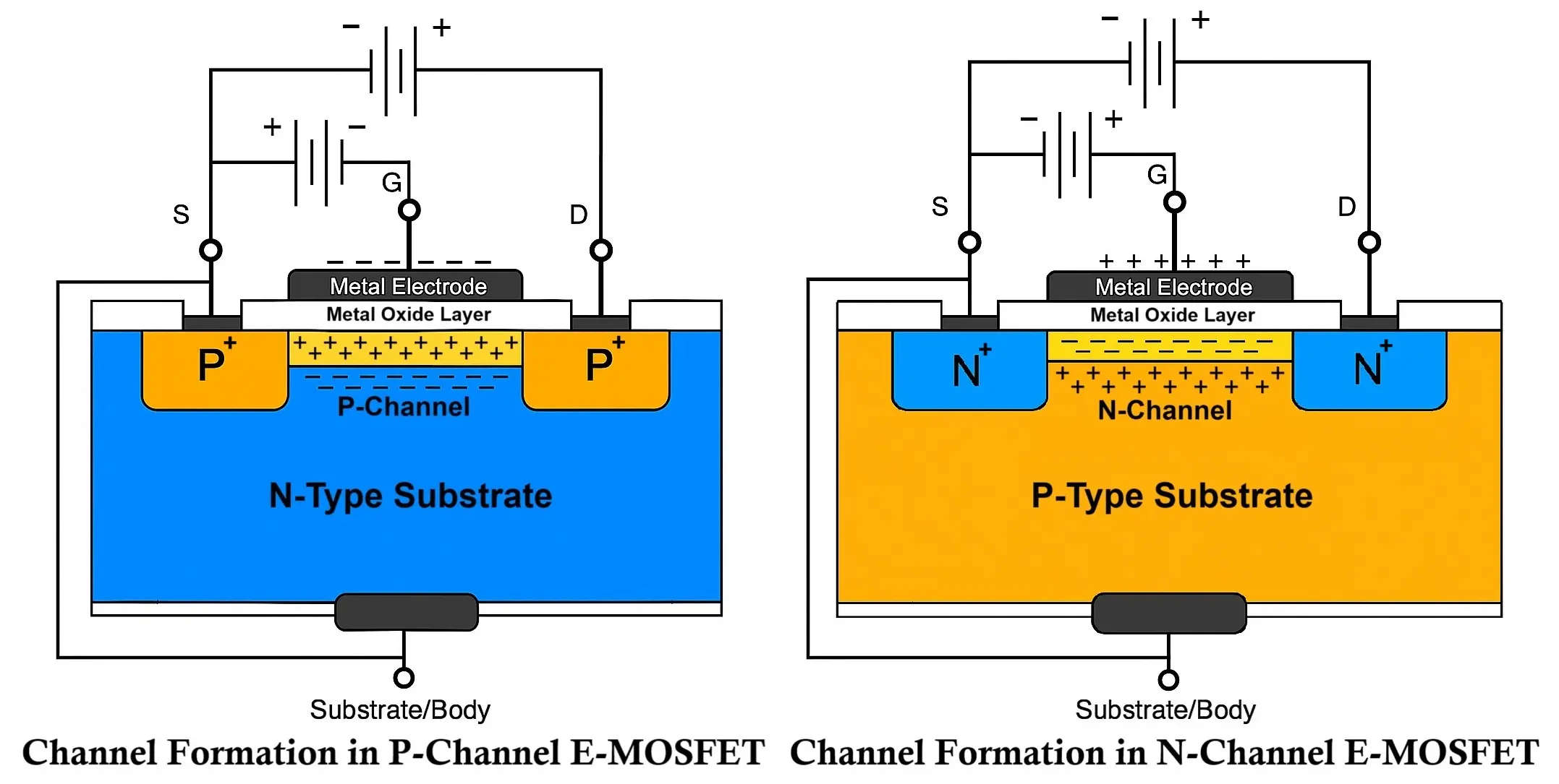
Working of E-MOSFET (Enhancement Type MOSFET):
Unlike D-MOSFETs, E-MOSFETs rely solely on the enhancement mode of operation. No current flows unless a gate voltage of sufficient magnitude is applied to induce an inversion layer that acts as a conducting channel.
N-Channel E-MOSFET Operation
1. VGS = 0V (OFF State)
- There is no n-type channel between source and drain.
- P-type substrate prevents current flow.
- The device is OFF.
2. VGS > 0V (Enhancement Mode)
- A positive voltage applied to the gate creates an electric field.
- This field attracts electrons (minority carriers in p-substrate) toward the gate area.
- When VGS exceeds a certain level called the threshold voltage (VTh), enough electrons gather to form an inversion layer or n-channel.
- Once the channel forms, current can flow from drain to source if a voltage VDS is applied.
Above VTh, increasing VGS increases channel conductivity and current ID.
P-Channel E-MOSFET Operation
1. VGS = 0V (OFF State)
- No p-channel exists.
- No conduction occurs between drain and source.
2. VGS < 0V (Enhancement Mode)
- A negative voltage applied to the gate attracts holes (minority carriers) toward the gate region in the n-type substrate.
- At a sufficiently negative VGS (less than VTh), holes accumulate to form a p-type inversion layer (channel).
- Current can flow between source and drain if VDS is applied.
Symbols of Enhancement-Type MOSFETs
E-MOSFET symbols feature a broken line between source and drain, indicating the absence of a physical channel at VGS = 0V.

- Arrow in = N-channel
- Arrow out = P-channel
The arrow shows the direction of conventional current flow in the substrate.
Comparison of N-Channel E-MOSFET and P-Channel E-MOSFET
| Parameter | N-Channel E-MOSFET | P-Channel E-MOSFET |
|---|---|---|
| Substrate type | P-type | N-type |
| Charge carriers | Electrons | Holes |
| Channel formation | Induced by +VGS | Induced by –VGS |
| Threshold voltage | Positive | Negative |
| Normally ON/OFF | OFF | OFF |
| Gate bias to turn ON | Positive | Negative |
- Enhancement-type MOSFETs (E-MOSFETs) do not have a conducting channel at zero gate voltage.
- They turn ON only when a threshold gate voltage is exceeded, inducing a channel between source and drain.
- N-channel E-MOSFETs require a positive VGS, while P-channel E-MOSFETs require a negative VGS.
- Due to their normally OFF nature and low leakage, they are ideal for digital logic and power switching applications.
Differences Between Depletion and Enhancement MOSFET
Here is a comparison between Depletion MOSFET (D-MOSFET) and Enhancement MOSFET (E-MOSFET).
| Feature | Depletion MOSFET (D-MOSFET) | Enhancement MOSFET (E-MOSFET) |
|---|---|---|
| Definition | A MOSFET where the channel exists by default and can be depleted by gate voltage. | A MOSFET where the channel is created (enhanced) by applying gate voltage. |
| Channel at Fabrication | Channel is already formed during manufacturing. | No channel exists during manufacturing. |
| Default State (No Gate Voltage) | Normally ON – it conducts even when VGS = 0. | Normally OFF – it does not conduct when VGS = 0. |
| Reverse Gate Voltage | Narrows or depletes the channel, reducing current. | Has no effect (no channel to deplete initially). |
| Forward Gate Voltage | Enhances the channel, increasing current. | Creates and enhances the channel to start conduction. |
| Operating Modes | Works in both depletion and enhancement modes. | Works only in enhancement mode. |
| Switching Behavior | Turns OFF with reverse biasing of gate. | Turns ON with forward biasing of gate above threshold. |
| Threshold Voltage (Vth) | No minimum voltage required to turn ON; it’s already conducting by default. | Requires a threshold voltage to turn ON. |
| Subthreshold Leakage | No threshold voltage | Can have subthreshold leakage current between source and drain. |
| Symbol Difference | Channel line is solid (indicates existing channel). | Channel line is broken or missing (indicates no initial channel). |
| Typical Use | Analog circuits, RF amplifiers, variable resistors. | Digital switching, logic gates, microprocessors, power electronics. |
Advantages of Depletion type MOSFET D-MOSFET:
- Can operate in both enhancement and depletion modes
→ D-MOSFETs can conduct with 0V gate voltage (depletion mode) and increase current flow with positive gate voltage (enhancement mode). This dual-mode operation provides flexibility in circuit design. - Normally ON device
→ Unlike E-MOSFETs, a D-MOSFET conducts current when the gate-source voltage (VGS) is zero. This makes it useful for fail-safe designs or analog applications where a default ON state is required. - High input impedance
→ The gate is insulated from the channel, so very little current is needed to control it. This prevents loading of the previous stage in analog circuits. - Good for analog applications
→ D-MOSFETs behave like a voltage-controlled resistor, making them excellent for signal processing tasks such as amplifiers, tone controls, or voltage-controlled attenuators. - Fast switching speed
→ The lack of a PN junction at the gate (due to its insulated nature) allows for very quick switching times, suitable for high-frequency applications like RF amplification.
Disadvantages of Depletion type MOSFET D-MOSFET:
- Always conducting at VGS = 0
→ Since the channel is already formed, it requires a negative VGS (in n-channel) to reduce or cut off current flow. This may complicate switching applications. - Less common and harder to find
→ E-MOSFETs have largely replaced D-MOSFETs in many applications, making them less available in the market and harder to source. - More complex biasing
→ To turn the device OFF or reduce its current, you need to apply a negative gate voltage, which requires an additional biasing circuit. - Lower market adoption
→ Because they are less widely used, there’s less support, fewer models, and limited documentation compared to enhancement MOSFETs.
Applications of Depletion type MOSFET D-MOSFET:
- Analog signal processing – Acts like a variable resistor in analog circuits.
- Amplifiers (RF and audio) – Works well in linear amplifier stages due to continuous current control.
- Automatic gain control circuits – Can adjust signal strength based on input conditions.
- Analog switches – Acts as a controllable switch with low on-resistance.
- Voltage-controlled resistors – Used in circuits where the resistance must change with voltage.
Advantages of Enhancement type MOSFET E-MOSFET:
- Normally OFF
→ No current flows when VGS = 0, making them ideal for digital logic and power switching where the default state should be OFF. - Simple biasing
→ Only requires a positive (n-channel) or negative (p-channel) gate voltage to turn ON, which simplifies the control circuitry. - Lower leakage currents
→ The insulated gate ensures negligible leakage, making them energy efficient and great for battery-powered devices. - Widely available and cost-effective
→ Due to high demand in digital electronics and power systems, they are mass-produced, lowering costs and ensuring wide availability. - High-speed switching
→ The gate capacitance is low, so it charges and discharges quickly, allowing fast switching for digital and high-frequency circuits.
Disadvantages of Enhancement type MOSFET E-MOSFET:
- Cannot conduct at VGS = 0
→ Since no channel exists by default, you must apply a threshold voltage to turn the device ON. This can be limiting in low-voltage or analog applications. - Susceptible to static discharge damage
→ The insulated gate oxide is thin and sensitive; static electricity can permanently damage it unless precautions are taken. - Gate threshold voltage needed to turn ON
→ Requires a minimum gate voltage (Vth) to conduct. If your circuit operates near this voltage, the MOSFET might not switch fully ON. - More limited use in analog applications
→ Because the current increases non-linearly with gate voltage, it’s less suitable for analog signal amplification than depletion-mode devices.
Applications of Enhancement type MOSFET E-MOSFET:
- Digital switching (CMOS logic) – Used in processors, memory, and logic gates where fast, efficient switching is crucial.
- Power electronics (inverters, converters) – Used as high-efficiency switches in power supplies and motor drivers.
- Microcontroller I/O switching – Commonly used to drive LEDs, relays, and other peripherals from microcontroller outputs.
- Motor drivers – Works well in H-bridge configurations to control motors.
- Load switches – Used to connect/disconnect power to specific parts of a circuit efficiently.
Conclusion:
-
- MOSFETs are essential semiconductor devices used in all modern electronics.
- D-MOSFETs offer both depletion and enhancement mode operation and are suited for analog applications.
- E-MOSFETs are more common in digital and power electronics due to their normally OFF nature and energy efficiency.
- Understanding the construction, working, and difference between D-MOSFET and E-MOSFET is crucial for choosing the right MOSFET in circuit design.
Popular Enhancement Type MOSFETs: BS107, BS108, 2N7000, IRFZ44N.
Popular Depletion Type MOSFETs: IXTP01N100D, CPC3710, DN2540, LND150.
IGBT Full Form, Symbol, Construction, Working and Applications
JFET Junction Field Effect Transistors Working and Applications
