CD4029 is a Synchronous, Programmable, Presettable, 4 Bit Up/Down & Binary/Decade counter which is very much similar to the IC 74193, However, there is one notable change between IC74193 and CD4029: CD4029 has one unique pin that determines its counter configuration for Binary and BCD counter mode, allowing the IC to count similarly to binary counter ICs such as 74163, 74193, and 74169, as well as BCD (Decade), counter ICs such as 74160, 74190, and 7490. It features a single terminal that controls the Up/Down counter mode. Find most basic detail on counter.
Feature of CD4029-:
- 4-Bit presettable inputs pins.
- Up/Down Binary counting & Up/Down BCD (Decade) counter.
- Wide supply voltage range 3v to 15v.
- Operating temperature range (-40 to +85) Degree Celsius
- High noise immunity 0.45VDD (typically).
- Low power TTL compatibility: fan out of 2 driving 74L or 1 driving 74LS.
- Programmable Up/Down & Binary/Decade counter.
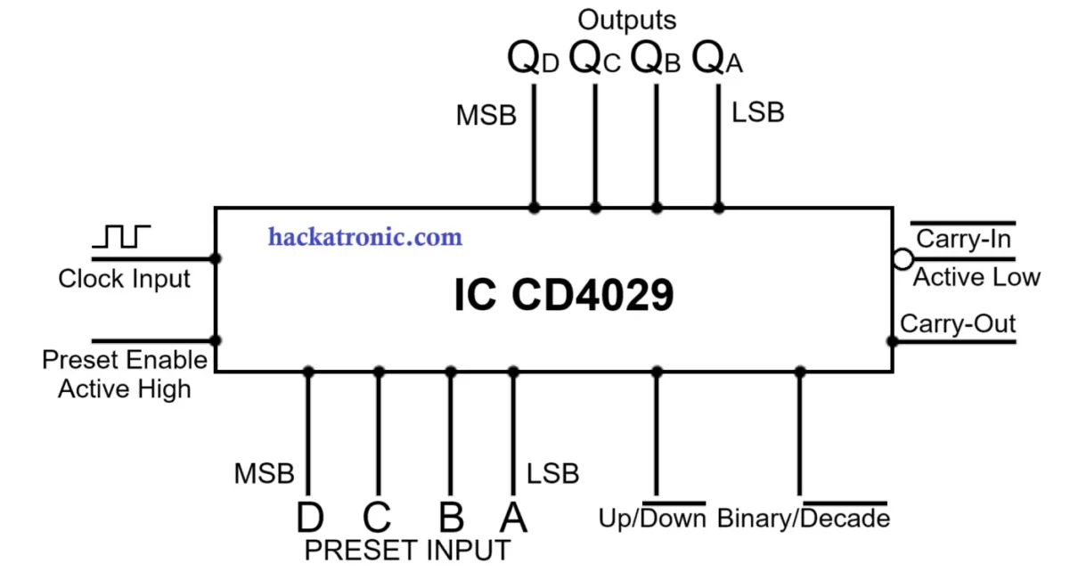
CD4029 Block Diagram-:
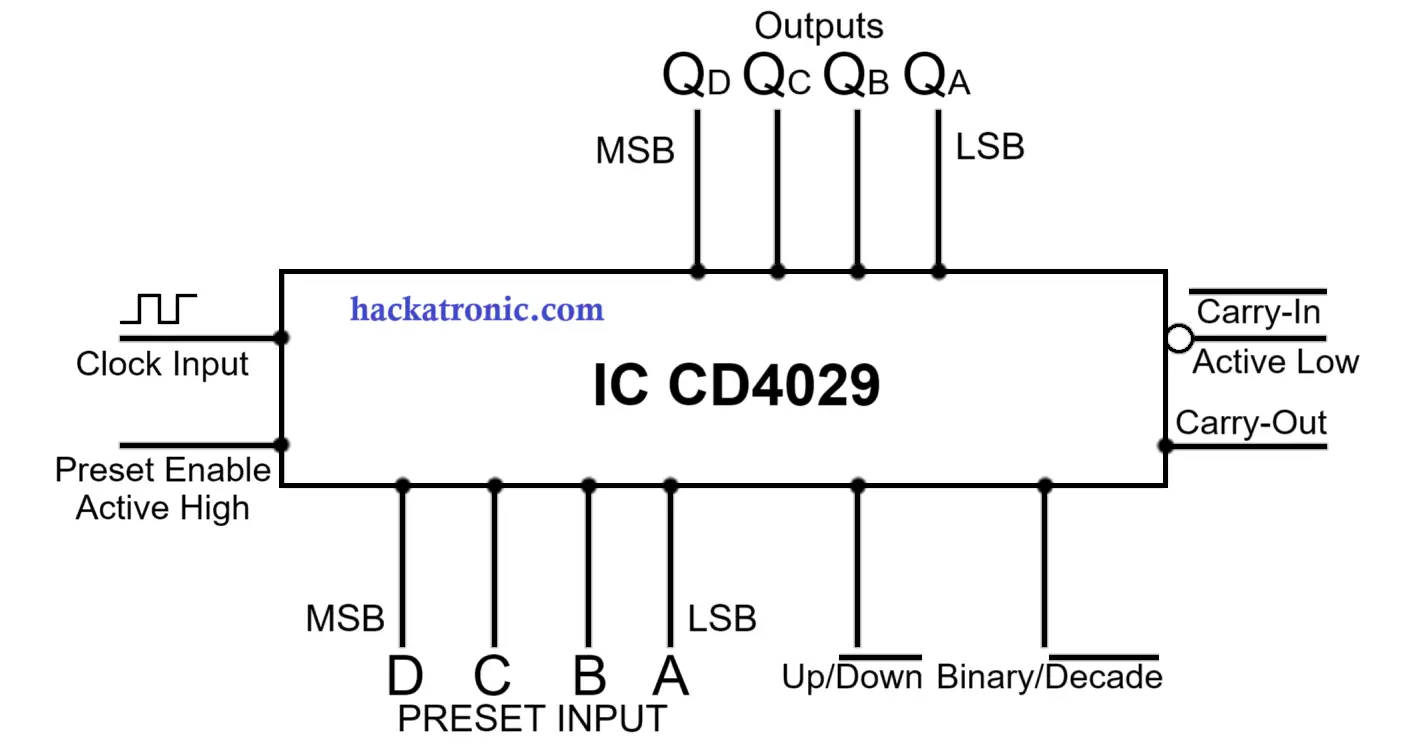
The short pin descriptions are provided in the table below; detailed functional descriptions of each pin are provided in the next section, so continue reading to the conclusion.
| Pin | Description |
| Clock input | Clock signal input |
| Preset Enable (Active High) | Used to Load the Data of A, B, C, & D input pins |
| Up/Down | Toggle the Up & Down counter mode. |
| Binary/Decade | Toggle the Binary & Decade counter mode. |
| Carry Out | At its maximum and minimum count, it transitions from logic 1 to logic 0. |
| Carry-In | Used in the cascading, also trigger IC for counting at logic 0 |
| A, B, C, & D | Preset Inputs (Parallel Data Inputs) |
| Qn | Flip-Flop Outputs |
CD4029 Technical Description of Pins-:
clock Input -:
-:
- It is also known as clock pulse/clock signal, its continuous high-low signal which will use to trigger IC, that’s why it is also known as triggering pulse.
- All 4 flip-flops are triggered with the same clock signal in this IC or any synchronous counter.
Active High preset input-:
- This pin is most commonly used to load data from terminals A, B, C, and D (jam inputs).
- This pin works asynchronously with the clock signal and loads data to the outputs irrespective of clock inputs
- Logical 0 should be applied to the preset enable input to start counting of IC CD4029. Otherwise, it will not increment its counting.
- If logical 1 is applied to the preset enable input, then whatever information available to its jam (A, B, C, D) inputs will be transferred to the outputs.
- If count 5 (0101) is present to its jam (A, B, C, D) inputs and logic 0 is applied to the preset input, the counting will be unaffected, and the IC will continue to count on each positive edge of the clock.
- If count 5 (0101) is present to its jam (A, B, C, D) inputs and logic 1 is applied to the preset input, then the IC will not count with positive-Edge of the clock signal, it inhibits counting. And its loads asynchronously count 5 (0101) to the outputs (Qa, Qb, Qc, Qd) terminals, which means it’s completely independent of the clock signal.
What is meant by Asynchronous-;
- The counting which is not synced with the positive edge of the clock signal is known as Asynchronous Counting, or in other words, you can say that the counter will not change its state according to the clock signal is known as an asynchronous counter.
- IC CD4029 is also had asynchronous active high preset input, Which will inhibit counting when this terminal will be supplied with a high value (logic 1).
- It is completely independent of the clock signal.
- If this terminal has logic 1 is applied then it will load the data present at jam input (A, B, C, D) to the outputs, after each clock pulse.
Up/Down Terminal-:
- This terminal is used to toggle counter mode as either up counting or down counting.
- Logic 1 should be applied for Up counting (The count will increment after each clock signal).
- Logic 0 should be applied for Down counting (The count will decrement after each clock signal).
Binary/Decade Terminal-:
- The Binary and Decade modes can be selected with appropriate input at this terminal.
- Logic 1 should be applied for Binary Counting (Binary Counter has 16 unique states i.e 0-15 -> (0000 to 1111)).
- Logic 0 should be applied for Decade Counting (in Decade Counter has 10 unique states i.e 0-9 -> (0000 to 1001)).
Carry-Out -:
- This terminal toggles between logic 0 & logic 1.
- At its, maximum & minimum count it switches from logic 1 to logic 0, as mentioned below.
- Binary/Up counter Mode => reached max count (1111) => switched to logic 0.
- Binary/Down counter Mode => reached min count (0000) => switched to logic 0.
- Decade/Up counter Mode => reached max count (1001) => switched to logic 0.
- Decade/Down counter Mode => reached min count (0000) => switched to logic 0.
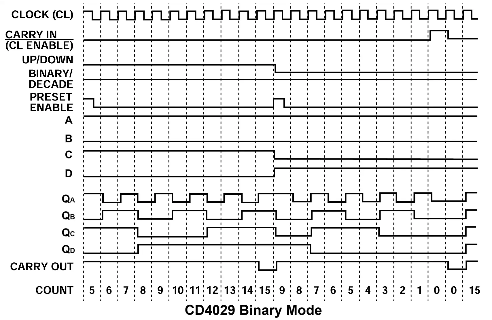
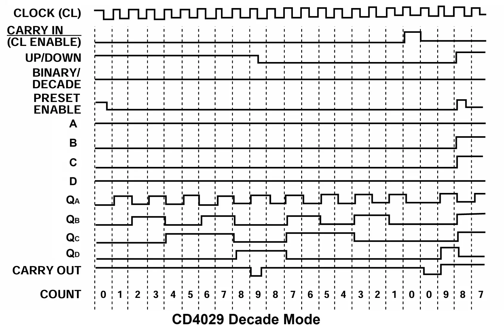
- This terminal is most useful in cascading 2 or more CD4029 ICs, In cascading the output of this pin is connected to the Carry-In terminals of successive CD4029. the same will be reflected in the attached logical waveform figures 1A & 1B
Carry-In (Active low)-:
- To increment counting this pin should be connected with logic 0.
- If the carry-in and preset enable inputs are both logical “0,” the counter is advanced one count at the positive-going edge of the clock. When either or both of these two inputs are at logical “1,” advancement is stopped.
- In Cascading this pin is getting input from the carry-out pin, as the carry-out pin switches to logic 0, and at logic 0 carry-in terminal allows successive CD4029 to increment its counting that is why these two pins are coupled in the cascading.
- Logic 0 at Carry-in & Preset inputs => Increment/decrement counting.
Preset inputs (A, B, C, D)-:
- A B, C, & D are the preset input, in which A is the Least Significant Bit (LSB), and D is the Most Significant Bit (MSB).
- To load the data present at preset inputs, we should apply logic 1 to the preset enable pin. And logic 1 should be applied logically so that it loads the data of pins A, B, C, & D only once in the cycle and does not affect the counting sequence.
- Basically, these preset inputs are used to load data when you want to begin your counting from a specific number.
- If you have a task to count people entering a classroom, you will not start counting from 0; instead, you will start counting from 1. where you can use the preset inputs to begin counting from 1 (i.e you will load 0001 at D, C, B, A). and apply logic 1 only at the beginning of counting, once the counting is started immediately logic 0 should be supplied to the preset enable terminal. for this, you can use logic gates. you can check a mod 7 counter in which we have applied high & low logic when required.
Flip-flop outputs-:
- Qa, Qb, Qc, & Qd are the output terminals in which Qa is the Least Significant Bit (LSB) and Qd is the Most Significant Bit (MSB).
CD4029 Logical Waveform for Binary Mode-:
CD4029 Logical Waveform for Decade Mode-:
Check out our other articles on the counter circuit…👇👇👇👇👇👇👇👇👇👇
IC 74163, IC 74160, IC 7493, IC 74193, IC 7490, Counter Circuit using 555 timer
Happy Learning…
Difference Between Synchronous and Asynchronous Sequential Circuits

Thank so much for such wonderful content. I loved the way you planned everything:
This is an excellent and comprehensive breakdown of the CD4029 — a truly versatile IC that brings together binary and BCD counting in a single programmable package. The ability to toggle between up/down modes and binary/decade configurations with simple logic inputs makes the CD4029 ideal not just for educational and hobbyist projects but also for more complex timing and control systems.