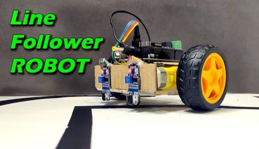
Hey, folks in this project we will be making a line follower robot using Arduino Uno. As a beginner in robotics, making a line follower robot is a good idea. By this, you can learn how a robot works?
A line follower robot follows a black line over a white surface using its two IR sensors. Similarly, we can make a robot that does the opposite, it will follow a white line over a black surface.
Working of IR sensor:
In this circuit, the output of the infrared sensor is most important while making any decisions by the Arduino. IR sensor has an IR transmitter and an IR receiver. Both are placed together.
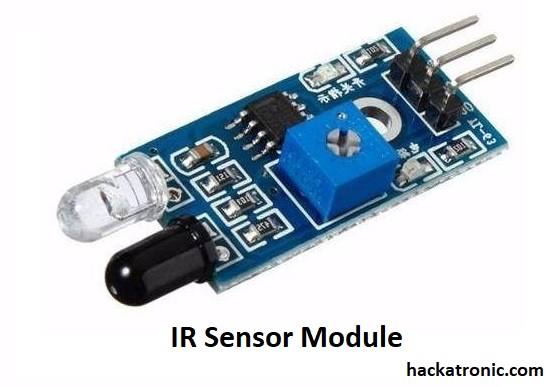
The IR LED emits infrared rays, This light travels in the forward direction. When an obstacle comes in front of the IR sensor, it reflects the light towards the sensor.
The IR sensor (photodiode) present alongside IR LED senses the light and becomes On. The photodiode is used in the reverse-biased mode so when light falls, it starts conducting current. The amount of current depends on light intensity.
The photodiode gives its output to a comparator circuit using an opamp like LM358. Depending on the input voltage comparator circuit gives a High or Low output. The microcontroller uses this signal to make a decision.
Motor driver L293D working:
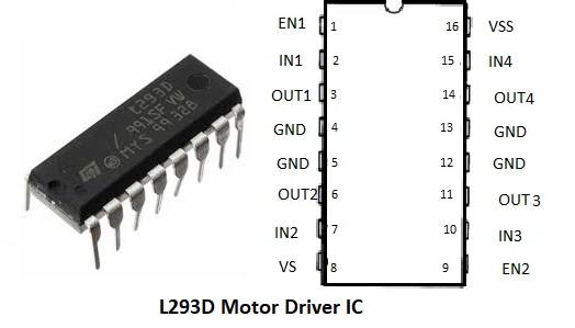
L293D is a dual H – bridge motor driver IC, it can drive two DC motors simultaneously. This IC can be directly connected to the Arduino and motor. Depending upon the input from Arduino it can drive the motor in forward or reverse direction. There are many motor driver boards available which uses L293D IC.
Dual Shaft Bo Motor:
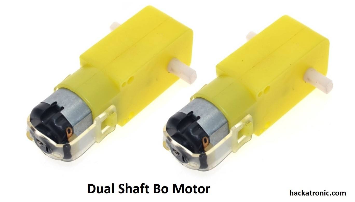
A dual shaft Bo Motor had gears to reduce the rotation speed of tyres. Here we need two motors with tyres and a bearing tyre. Making it a three-wheeler robot.
Components required for line follower robot:
- Bo Motor x 2
- Tyres x 2
- IR sensor module x 2
- chassis (you can make your own)
- Arduino (Uno, min or pro mini anything will be ok)
- L293D Motor Driver IC
- Wires
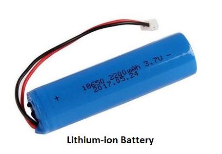
- Battery pack
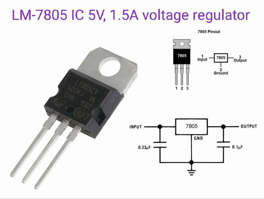
- Voltage regulator LM7805
Working of line follower robot using Arduino:
Let us understand the working of line follower robot using Arduino code.
#define s1 1
#define s2 2
#define l1 10
#define l2 4
#define r1 5
#define r2 6
#define e1 9
#define e2 3
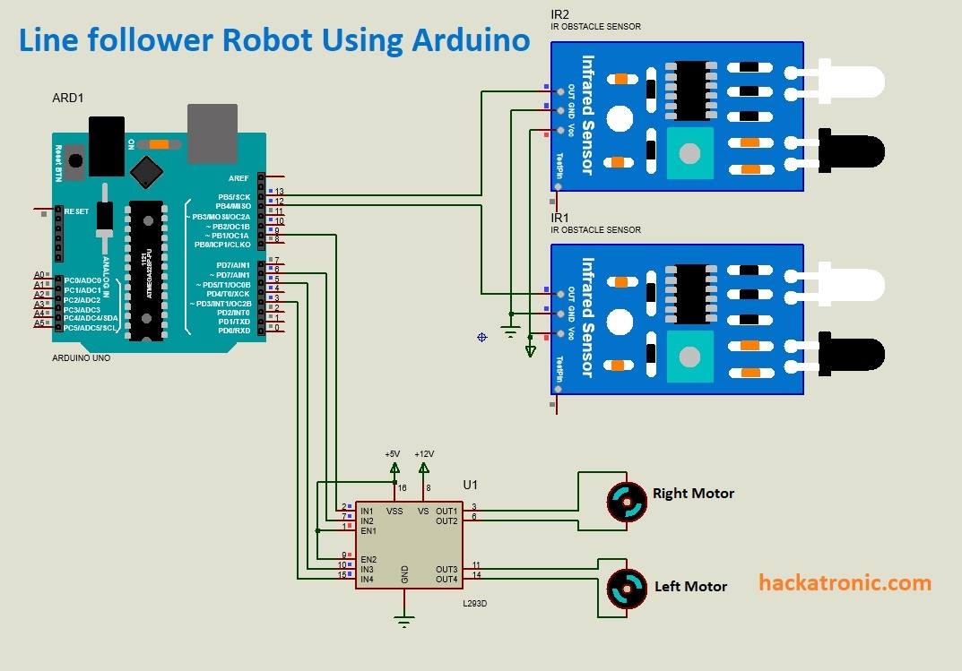
Here we are defining pins of the IR sensor and motor driver IC. s1 and s2 are the input pins of two Infrared sensor modules. l1 and l2 are the output pins for the right motor while r1 and r2 are the output pins for the left motor. e1 and e2 are the enable pins for both motors.
void setup()
{
pinMode(s1, INPUT);
pinMode(s2, INPUT);
pinMode(l1, OUTPUT);
pinMode(l2, OUTPUT);
pinMode(r1, OUTPUT);
pinMode(r2, OUTPUT);
pinMode(e1, OUTPUT);
pinMode(e2, OUTPUT);
}
In the void setup loop, we have declared functions of Arduino pins as either input or output.
void loop(){
To control the speed of the line follower robot, we have used a potentiometer and PWM signal. Depending upon the value of the potentiometer duty cycle varies. The PWM output is given at enable pin of the motor driver IC.
int potValue = analogRead(A0);
int pwmOutput = map(potValue, 0, 1023, 50, 255);
analogWrite(e1, pwmOutput);
analogWrite(e2, pwmOutput);
To drive the robot in forward direction output of both the IR sensors must be high.
if(digitalRead(s1)&&digitalRead(s2)){
digitalWrite(l1, HIGH);
digitalWrite(l2, LOW);
digitalWrite(r1,HIGH);
digitalWrite(r2, LOW);
}
If the left sensor gives a low output then the robot will make a left turn.
if(!(digitalRead(s1))&&digitalRead(s2)){
digitalWrite(l1, LOW);
digitalWrite(l2, LOW);
digitalWrite(r1,HIGH);
digitalWrite(r2, LOW);
}
The robot will make a right turn If the right sensor gives a low output.
if(digitalRead(s1)&&!(digitalRead(s2))){
digitalWrite(l1, HIGH);
digitalWrite(l2, LOW);
digitalWrite(r1,LOW);
digitalWrite(r2, LOW);
}
If the output of both the sensors becomes low the robot will automatically stop.
if(!(digitalRead(s1))&&!(digitalRead(s2))){
digitalWrite(l1, LOW);
digitalWrite(l2, LOW);
digitalWrite(r1,LOW);
digitalWrite(r2, LOW);
}
}
code for line follower robot
#define s1 1
#define s2 2
#define l1 10
#define l2 4
#define r1 5
#define r2 6
#define e1 9
#define e2 3

void setup()
{
pinMode(s1, INPUT);
pinMode(s2, INPUT);
pinMode(l1, OUTPUT);
pinMode(l2, OUTPUT);
pinMode(r1, OUTPUT);
pinMode(r2, OUTPUT);
pinMode(e1, OUTPUT);
pinMode(e2, OUTPUT);
}

int potValue = analogRead(A0);
int pwmOutput = map(potValue, 0, 1023, 50, 255);
analogWrite(e1, pwmOutput);
analogWrite(e2, pwmOutput);

if(digitalRead(s1)&&digitalRead(s2)){
digitalWrite(l1, HIGH);
digitalWrite(l2, LOW);
digitalWrite(r1,HIGH);
digitalWrite(r2, LOW);
}

if(!(digitalRead(s1))&&digitalRead(s2)){
digitalWrite(l1, LOW);
digitalWrite(l2, LOW);
digitalWrite(r1,HIGH);
digitalWrite(r2, LOW);
}

if(digitalRead(s1)&&!(digitalRead(s2))){
digitalWrite(l1, HIGH);
digitalWrite(l2, LOW);
digitalWrite(r1,LOW);
digitalWrite(r2, LOW);
}

if(!(digitalRead(s1))&&!(digitalRead(s2))){
digitalWrite(l1, LOW);
digitalWrite(l2, LOW);
digitalWrite(r1,LOW);
digitalWrite(r2, LOW);
}
}
You can COPY the code for your reference. Thanks for reading, do share and comment if you have any doubts.

Very good
THANKS MY FRIEND FOR THE HARD WORK can you please check the code link it gives me error i cant access to it