In this project, we will see how to make a triangle wave generator using the 555 timer IC. 555 timer is a very versatile delay and square wave generator IC. It one of the most used ic in electronics projects.
You might have used or seen a waveform generator. It is an instrument that can generate various types of waveforms like a square wave, triangle wave Sine wave ramp signal, and many other waveforms.
You can also generate triangle waves using opamp but the circuit becomes a little complex. Here we are using 555 timer it is easier to use and understand than the opamp circuit.
Triangle wave generator circuit:
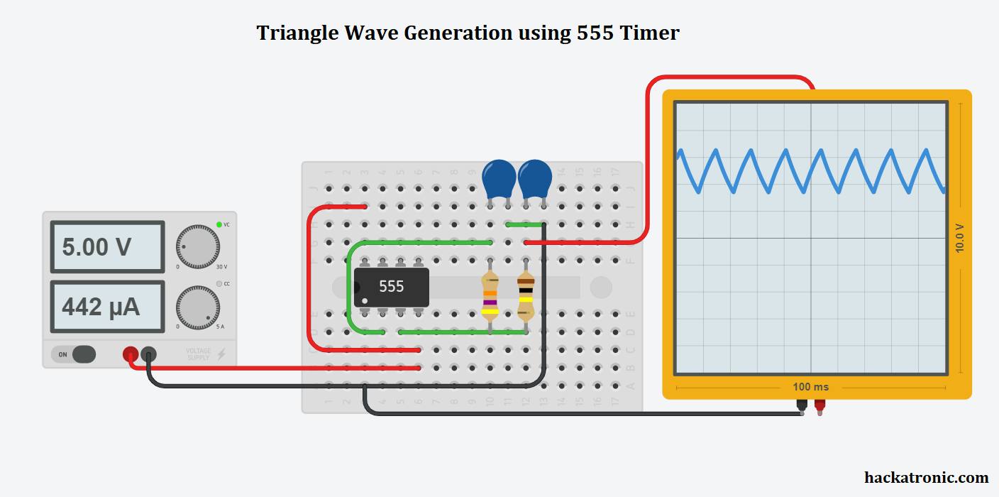
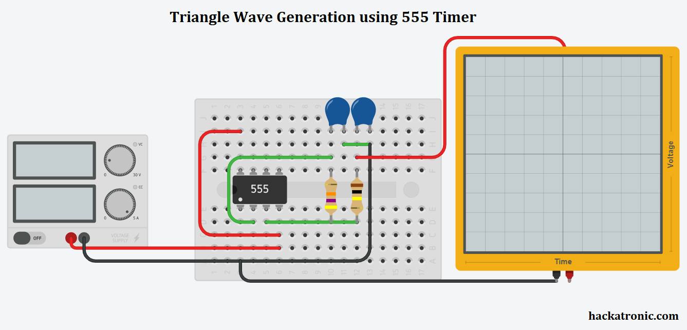
This is a breadboard simulation of a triangle wave generator on tinkercad online software. You can use this software to simulate simple electronics circuits.
Circuit Components:
- 555 timer IC
- 1uf capacitor
- 0.5uf capacitor
- 47k ohm resistor
- 100k ohm resistor
- Power supply
- Oscilloscope to see the waveform
Circuit explanation:
This is a very simple circuit consisting of a 555 timer a pair of resistors and capacitors.
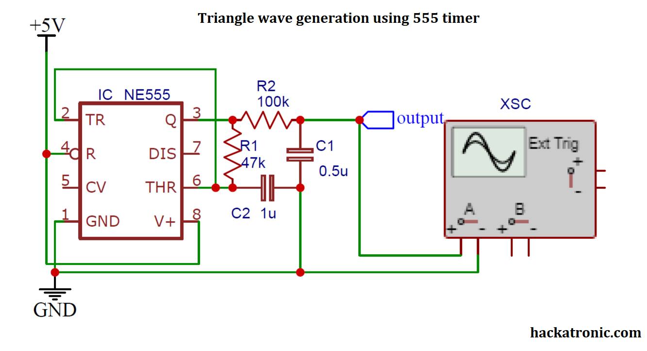
Pin 4 and 8 of the 555 timer are connected to +Vcc while pins 1 and 8 are connected to the ground. Pins 2 and 6 are shorted and a capacitor is connected to them. A 47k ohm resistor is connected between pins 3 and 6. The output is taken from pin 3 via a 100k resistor. A 0.5uf capacitor is connected to PIN 6.
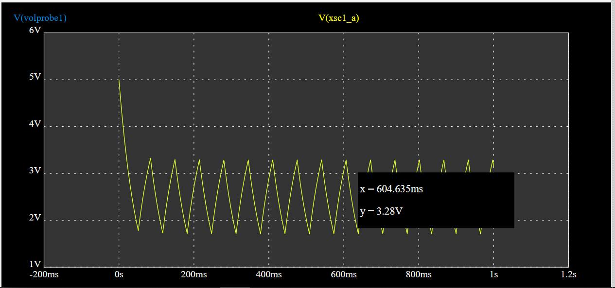
Output waveform:
Circuit Diagram of triangle wave generator:
Working of triangle wave generator using 555 timer:
In this circuit, the 555 timer is working in astable multi-vibrator mode. In this mode it continuously switches the output from low to high, making a square wave output.
The duty cycle of the square wave must be kept at 50%. If the square wave duty cycle is not 50% the triangle wave produced will be asymmetrical. The square wave output is generated at PIN 3.
This square wave is then passed to a capacitor of 0.5uf capacitance. When the output of the 555 timer goes high the capacitor starts charging making a raising edge of the triangle wave. Whereas when the output goes low the capacitor starts discharging through the load resistor, Making the falling edge of the triangle wave. If you carefully observe the waveform it is slightly curved due to the characteristics of the capacitor.
The shape of the triangle wave depends on the value of R and C so chose them correctly. Also, the frequency of this wave depends on the RC time constant. If you increase the value of the capacitor then the waveform will become more sharpen.
