Surface Mount Device (SMD) resistors, also called chip resistors, are among the most widely used passive components in modern electronic circuits. With the shift from through-hole technology (THT) to surface-mount technology (SMT), SMD resistors have become the industry standard for compact, high-density, and automated PCB assembly.
This article presents an in-depth, technical explanation of SMD resistors covering symbol, construction, working principle, electrical characteristics, value reading methods, types, selection criteria, advantages, disadvantages, applications, and a comprehensive summary table.
SMD Resistors
An SMD resistor is a fixed-value resistor designed to be mounted directly onto the surface of a printed circuit board (PCB) without requiring lead wires or drilled holes.

Why SMD Resistors Are Important
- Enable miniaturization of electronic products
- Compatible with automated pick-and-place assembly
- Provide better high-frequency performance
- Reduce PCB size, weight, and cost in mass production
SMD resistors are used in almost every modern electronic system, from smartphones and laptops to automotive ECUs and industrial control boards.
SMD Resistor Symbol
In circuit diagrams, SMD resistors use the same symbol as conventional resistors, since the symbol represents electrical behavior rather than physical construction.
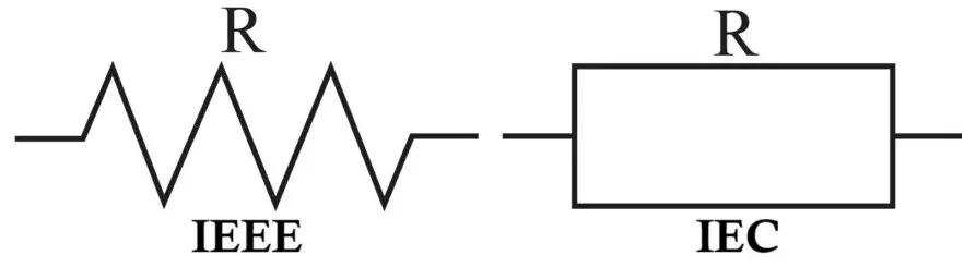
- Zigzag symbol (ANSI / US standard)
- Rectangular symbol (IEC / European standard)
There is no separate schematic symbol for SMD and through-hole resistors. The distinction is made only in the PCB footprint and bill of materials (BOM).
Related Articles:
- Fusible Resistor Construction, Working, Types and Applications
- Wire Wound Resistor Construction, Working, Types & Applications
- Carbon Composition Resistor Construction, Working & Applications
- Carbon Film Resistor Construction, Working, Types & Applications
- Metal Film Resistor Construction, Working, Types and Applications
- Metal Oxide Resistor Construction, Working, Types & Applications
- Types of Resistors with Symbol, Classification and Applications
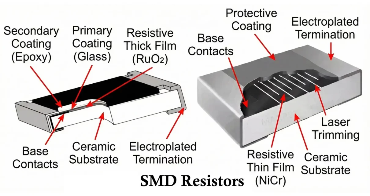
Construction of SMD Resistor
An SMD resistor is a multilayer precision component fabricated using thin-film or thick-film technology.
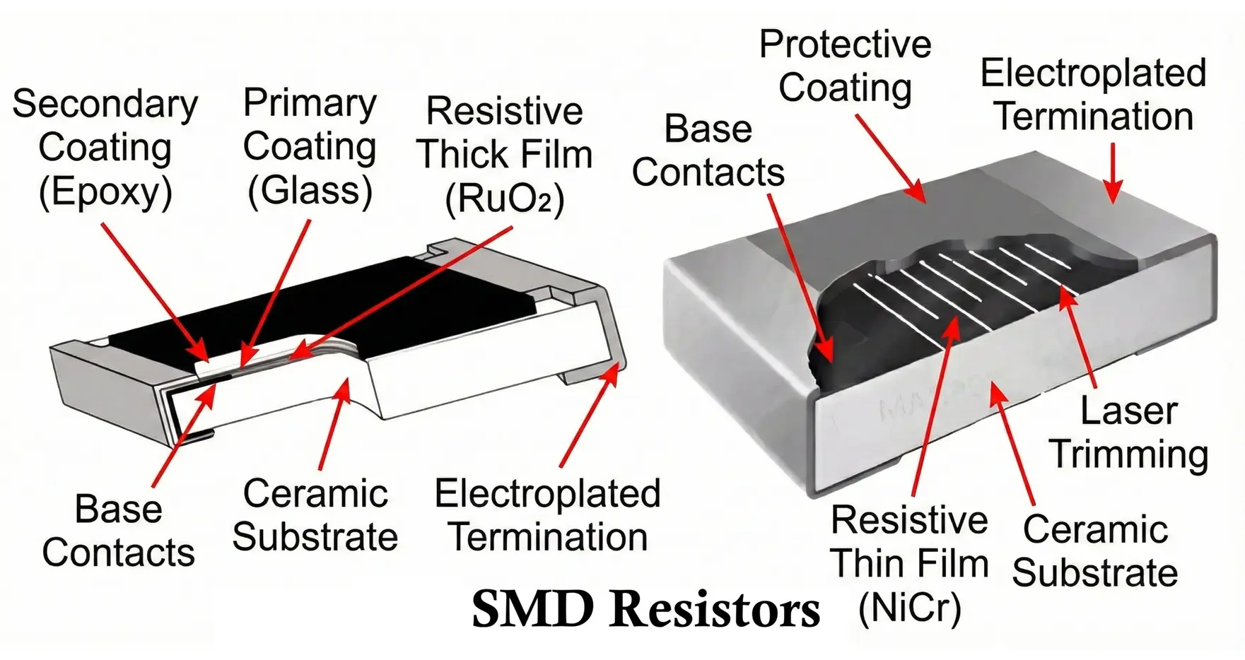
Main Construction Layers
- Ceramic Substrate
- Usually made from alumina (Al₂O₃)
- Provides mechanical strength and thermal stability
- Electrically insulating
- Resistive Element
- Made of metal oxide, ruthenium oxide, or metal alloy
- Deposited using thick-film screen printing or thin-film sputtering
- Resistance value controlled by geometry and material composition
- Termination Electrodes
- Silver or silver-palladium conductive layer
- Ensures low contact resistance
- Nickel Barrier Layer
- Prevents solder leaching
- Improves long-term reliability
- Tin Plating
- Provides solderability
- Compatible with lead-free soldering processes
- Protective Coating
- Glass or epoxy coating
- Protects resistive film from moisture and contamination
Working of SMD Resistor
SMD resistors work on the same fundamental principle as all resistors: opposition to the flow of electric current.
- When voltage is applied, electrons flow through the resistive element
- Collisions between electrons and atoms cause energy loss
- Energy is dissipated as heat
Governing Law
The operation follows Ohm’s Law:
V = I × R
- V = Voltage across resistor
- I = Current through resistor
- R = Resistance value
The physical size of an SMD resistor directly affects:
- Power dissipation capability
- Maximum operating voltage
- Thermal resistance
Characteristics of SMD Resistors
- Resistance Range
- Typically, from 0 Ω (jumper) to tens of megaohms
- Precision thin-film types offer tight tolerance at high values
- Power Rating
- Common ratings based on package size:
- 0402 → 1/16 W
- 0603 → 1/10 W
- 0805 → 1/8 W
- 1206 → 1/4 W
- 1210 and above → higher power
- Tolerance
- ±0.1%, ±0.25%, ±0.5%, ±1%, ±5%
- Thin-film resistors offer better tolerance than thick-film
- Temperature Coefficient (TCR)
- Expressed in ppm/°C
- Typical values:
- Thick film: ±100 to ±300 ppm/°C
- Thin film: ±5 to ±50 ppm/°C
- Noise Performance
- Thin-film SMD resistors generate lower electrical noise
- Important in audio and RF circuits
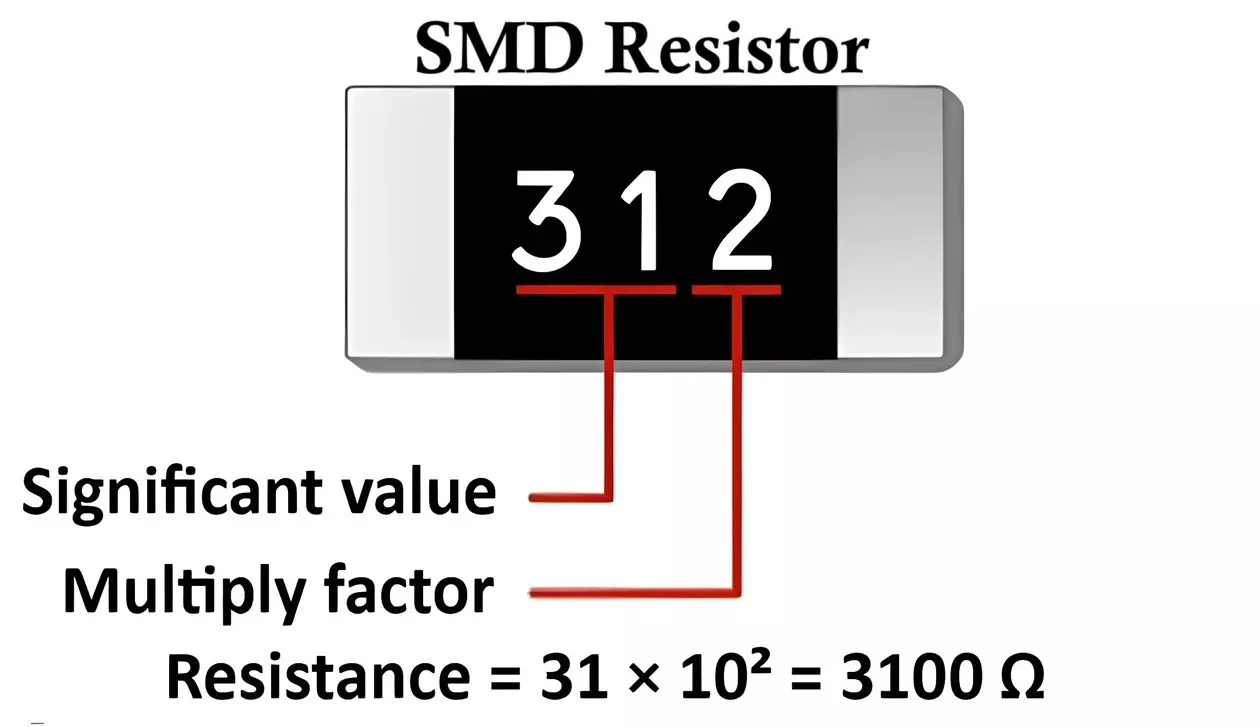
How to Read SMD Resistor Value
Unlike through-hole resistors, SMD resistors do not use color bands. Instead, numeric or alphanumeric codes are printed on larger packages. You can use SMD resistor code calculator to find value of 3 and 4 digit SMD resistor code.
-
- Three-Digit Code
- First two digits → significant figures
- Third digit → multiplier (power of 10)
- Example: 472 → 47 × 10² = 4700 Ω = 4.7 kΩ
- Four-Digit Code
- First three digits → significant figures
- Fourth digit → multiplier
- Example: 1001 → 100 × 10¹ = 1000 Ω = 1 kΩ
- “R” Notation
- Used to indicate decimal point
- Examples: 4R7 → 4.7 Ω, R22 → 0.22 Ω
- Three-Digit Code
- EIA-96 Code (Precision Resistors)
- Two digits + one letter
- Used for 1% and 0.1% tolerance resistors
- Requires EIA-96 lookup table
Types of SMD Resistors
- Thick Film SMD Resistor
- Most common and economical
- Moderate tolerance and TCR
- Used in general-purpose electronics
- Thin Film SMD Resistor
- High precision and stability
- Low noise and low TCR
- Used in instrumentation and RF circuits
- Metal Foil SMD Resistor
- Extremely low TCR
- Very high accuracy
- Used in calibration and aerospace systems
- Current Sense (Shunt) Resistor
- Very low resistance values (mΩ range)
- Used for current measurement
- High power and low inductance design
- Zero-Ohm SMD Resistor
- Act as jumpers or configuration links
- Simplify PCB routing
SMD Resistor Package Sizes
Common package sizes (imperial / metric):
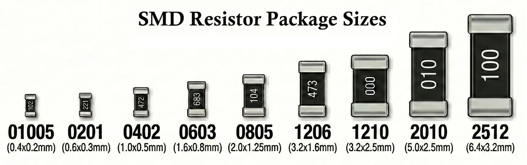
- 0402 (1005)
- 0603 (1608)
- 0805 (2012)
- 1206 (3216)
- 1210 (3225)
- 2512 (6432)
- Smaller packages:
- Save space
- Lower power handling
- Higher thermal stress sensitivity
Selection Criteria for SMD Resistors
When selecting an SMD resistor, consider the following factors:
- Electrical Requirements
- Resistance value
- Tolerance
- Power dissipation
- Maximum operating voltage
- Thermal Considerations
- PCB copper area for heat spreading
- Ambient temperature
- Derating requirements
- Performance Factors
- Temperature coefficient (TCR)
- Noise characteristics
- Long-term stability
- Mechanical and Manufacturing Factors
- Package size compatibility
- Reflow soldering profile
- Availability and cost
Advantages of SMD Resistors
- Compact size and lightweight
- Suitable for high-density PCB layouts
- Excellent high-frequency performance
- Automated assembly compatibility
- Reduced parasitic inductance and capacitance
- Improved reliability due to fewer mechanical joints
Disadvantages of SMD Resistors
-
- Difficult to handle manually
- Harder to replace or rework
- Limited power dissipation compared to large THT resistors
- Value markings absent on very small packages
- Requires precise soldering and PCB design
Applications of SMD Resistors
SMD resistors are used across almost all electronic industries:
- Consumer electronics (phones, TVs, laptops)
- Power supply and SMPS circuits
- Automotive electronics and ECUs
- Industrial control and automation
- Medical instruments
- RF and communication systems
- IoT and embedded systems
- Audio and signal conditioning circuits
Comparison with Other Resistor Types
- Size & mounting: SMD resistors are very small and surface-mounted; through-hole resistors are larger and require drilled holes.
- Manufacturing & cost: SMD parts are optimized for automated assembly and high-volume production; through-hole is slower and often costlier at scale.
- Electrical performance: SMD resistors typically have lower parasitic inductance/capacitance, making them better for high-frequency circuits.
- Power handling: Through-hole and wire-wound resistors generally handle higher power and heat than comparably sized SMD parts.
- Precision & stability: SMD (especially thin film) offers tight tolerances and good temperature stability; carbon composition is less stable and less precise.
- Repairability: SMD resistors are harder to probe and replace by hand; through-hole resistors are easier for prototyping and repairs.
- Applications: SMD dominates modern consumer electronics; through-hole and wire-wound are preferred for high-power, high-voltage, or rugged applications.
SMD Resistors Summary Table
| Parameter | Description |
|---|---|
| Component Type | Fixed passive resistor |
| Mounting Style | Surface mount |
| Resistance Range | 0 Ω to >10 MΩ |
| Power Rating | 1/16 W to several watts |
| Tolerance | ±0.1% to ±5% |
| TCR | ±5 to ±300 ppm/°C |
| Marking System | Numeric / alphanumeric codes |
| Common Packages | 0402, 0603, 0805, 1206 |
| Technologies | Thick film, thin film, metal foil |
| Major Applications | Consumer, industrial, automotive, RF |
Conclusion
Surface Mount (SMD) resistors are fundamental building blocks of modern electronics, offering compact size, excellent electrical performance, and manufacturing efficiency. Understanding their construction, characteristics, value coding, and selection criteria is essential for designing reliable and high-performance electronic circuits. As electronic devices continue to shrink while increasing in functionality, SMD resistors will remain indispensable in both commercial and industrial applications.
Types of Resistors with Symbol, Classification and Applications
Wire Wound Resistor Construction, Working, Types and Applications
Metal Film Resistor Construction, Working, Types and Applications
