A rheostat is a variable resistor specifically designed to control current in an electrical or electronic circuit without interrupting the circuit. Unlike potentiometers, which are mainly used for voltage division, rheostats are typically employed in series with a load to adjust current flow.
Rheostats are widely used in power control applications, such as motor speed control, lamp brightness control, heating element regulation, and laboratory testing circuits. Due to their ability to handle high current and power, rheostats are commonly built using wire-wound resistive elements.
Rheostat Symbol
The rheostat symbol is derived from the variable resistor symbol and consists of:
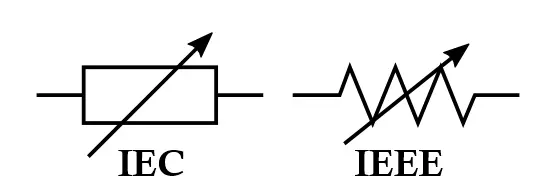
- A resistive element (zigzag or rectangular block)
- A sliding contact (wiper) shown as an arrow touching the resistive element
- Two terminals used in the circuit (one fixed terminal and the wiper)
Symbol Representation
- The arrow indicates the adjustable contact
- The resistive path shows variable resistance
- The unused terminal of the resistive element is usually left unconnected
Related Articles:
- Types of Resistors with Symbol, Classification and Applications
- Fusible Resistor Construction, Working, Types and Applications
- Wire Wound Resistor Construction, Working, Types & Applications
- Carbon Composition Resistor Construction, Working & Applications
- Carbon Film Resistor Construction, Working, Types & Applications
- Metal Film Resistor Construction, Working, Types and Applications
- Metal Oxide Resistor Construction, Working, Types & Applications
- SMD Resistors Construction, Working, Types and Applications
Construction of Rheostat
Basic Construction
A rheostat consists of the following major parts:
- Resistive Element
- Usually made of nichrome wire, constantan, or manganin
- Wound uniformly on a ceramic, porcelain, or fiberglass core
- Designed to withstand high temperatures and currents
- Sliding Contact (Wiper)
- Made of conductive metal or carbon
- Moves over the resistive wire
- Ensures smooth electrical contact without damaging the wire
- Terminals
- One terminal connected to one end of the resistive wire
- Second terminal connected to the movable wiper
- Mechanical Structure
- Rotary knob or linear slider
- Shaft and spring mechanism for pressure control
- Enclosed or open-frame design depending on application
High-Power Rheostat Construction
For industrial use:
- Large diameter wire
- Ventilated housing for heat dissipation
- Ceramic insulation
- Often mounted on metal frames with cooling fins
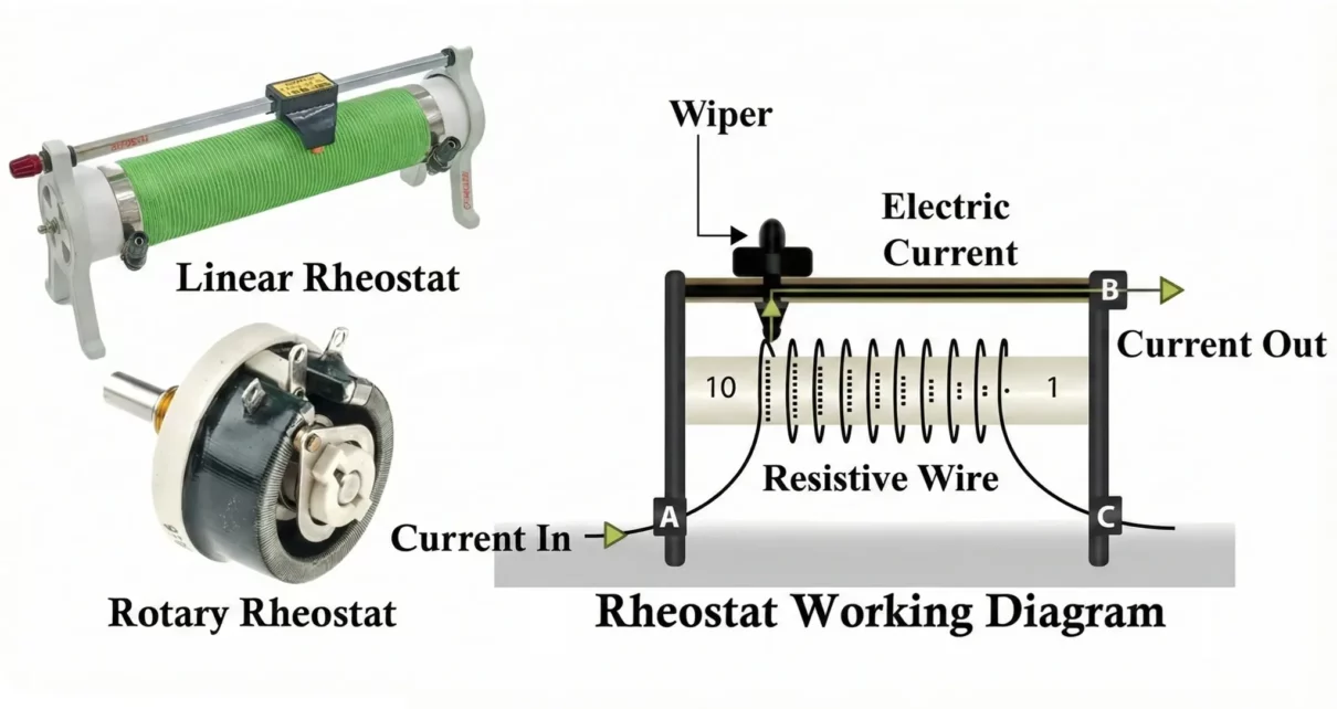
Working Principle of Rheostat
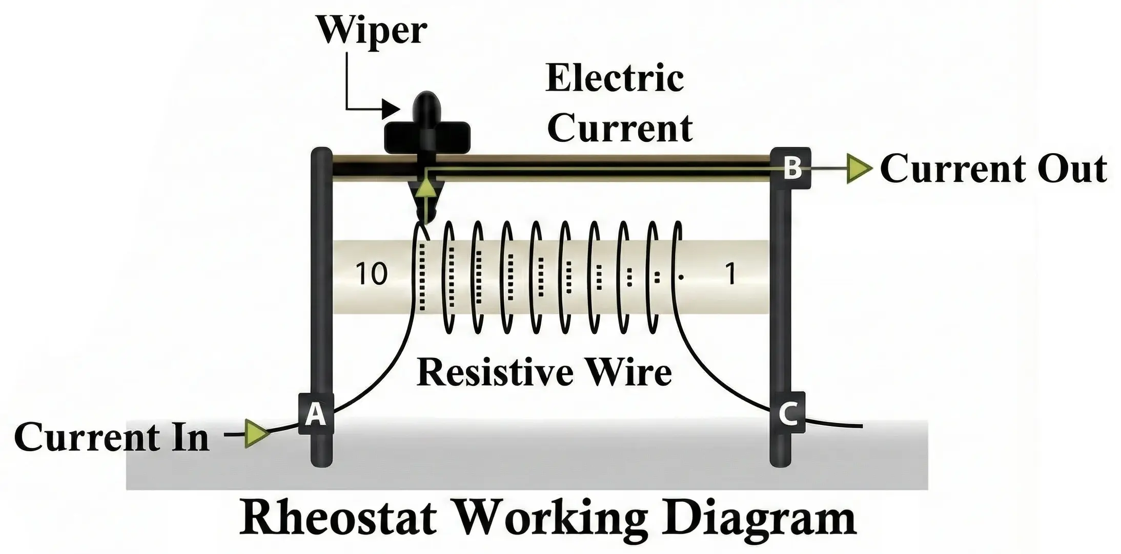
The working of a rheostat is based on Ohm’s Law:
I = V/R
Operating Principle
- The rheostat is connected in series with the load
- Moving the wiper changes the effective length of the resistive wire
- Increasing wire length → Higher resistance → Lower current
- Decreasing wire length → Lower resistance → Higher current
Step Vice Working
- Supply voltage is applied across the circuit
- Current flows through the rheostat and the load
- Rotating or sliding the control changes resistance
- Current adjusts accordingly
- Load behavior (speed, brightness, heat) changes smoothly
Characteristics of Rheostat
-
- Electrical Characteristics
- Resistance Range: From a few ohms to several kilo-ohms
- Current Rating: High (several amperes)
- Power Rating: Up to hundreds or thousands of watts
- Linearity: Mostly linear resistance change
- Mechanical Characteristics
- Smooth rotation or sliding motion
- Mechanical wear over time
- Adjustable resolution depends on wire turns
- Electrical Characteristics
- Thermal Characteristics
- Generates heat during operation
- Requires ventilation or heat sinking
- Temperature coefficient affects resistance value
How to Read Rheostat Value
Nameplate Markings
- Rheostat values are usually printed as: R / P
- Example:
100 Ω / 50 W
- Meaning: Maximum resistance = 100 ohms and maximum power dissipation = 50 watts
Additional Markings
- Current rating (e.g., 5A, 10A)
- Tolerance (±5%, ±10%)
- Manufacturer code
- Temperature rating
Practical Measurement
- Measure resistance using a multimeter
- Rotate shaft or move slide fully to verify minimum and maximum resistance
- Ensure smooth resistance variation without jumps
Types of Rheostats
Based on Construction
- Wire-Wound Rheostats
- Most common type
- High power handling
- Excellent stability
- Metal Ribbon Rheostats
- Flat resistive strips
- Lower inductance
- Used in control panels
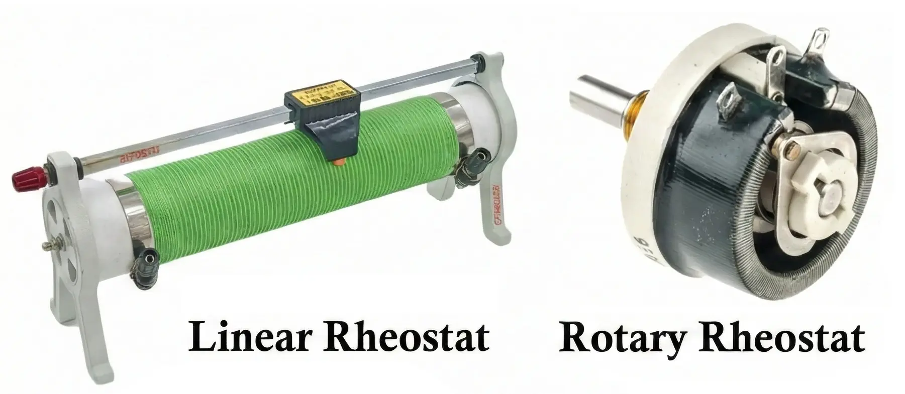
Based on Motion
- Rotary Rheostats
- Circular motion
- Knob-based adjustment
- Used in dimmers and motor controls
- Linear (Slide) Rheostats
- Slider movement
- Used in labs and testing equipment
By Applications
- Laboratory rheostats
- Industrial power rheostats
- Load bank rheostats
- Motor starting rheostats
- Preset rheostats
Rheostat Selection Criteria
- Electrical Parameters
- Required resistance range
- Maximum current
- Power dissipation capacity
- Supply voltage
- Mechanical Considerations
- Rotary or linear movement
- Mounting type
- Shaft length and knob compatibility
- Environmental Factors
- Ambient temperature
- Dust and humidity
- Continuous vs intermittent operation
- Safety Considerations
- Heat dissipation
- Insulation rating
- Short-circuit protection
Advantages of Rheostat
- Simple and robust design
- High current handling capability
- Smooth and continuous control
- Reliable and predictable behavior
- Easy to integrate into series circuits
- Suitable for harsh environments
Disadvantages of Rheostat
- Large size and weight
- Significant power loss as heat
- Lower efficiency compared to electronic controllers
- Mechanical wear over time
- Limited precision compared to digital control
- Not suitable for compact modern designs
Applications of Rheostat
- Electrical and Industrial Applications
- Motor speed control
- Generator field current control
- Load testing in power systems
- Welding current adjustment
- Electronic and Laboratory Applications
- Circuit testing and calibration
- Variable load simulation
- Educational experiments
- Analog control demonstrations
- Domestic and Commercial Uses
- Lamp dimming (older systems)
- Heating control
- Fan regulators (traditional)
Comparison: Rheostat vs Potentiometer
| Feature | Rheostat | Potentiometer |
|---|---|---|
| Main function | Current control | Voltage control |
| Circuit connection | Series | Parallel |
| Terminals used | 2 | 3 |
| Power handling | High | Low |
| Size | Large | Compact |
Summary Table
| Parameter | Description |
|---|---|
| Component type | Variable resistor |
| Primary function | Current control |
| Connection method | Series |
| Typical construction | Wire-wound |
| Resistance range | Low to medium |
| Power rating | High |
| Adjustment type | Rotary or linear |
| Main drawback | Power loss |
| Common applications | Motors, lamps, testing |
Conclusion
A rheostat is a fundamental current-controlling component in electrical engineering, especially where simplicity, reliability, and high-power handling are required. While modern electronic control methods have replaced rheostats in many applications, they remain indispensable in industrial systems, laboratories, and educational setups due to their intuitive operation and rugged design. Understanding rheostat construction, working principles, and selection criteria is essential for effective and safe circuit design.
Types of Resistors with Symbol, Classification and Applications
Wire Wound Resistor Construction, Working, Types and Applications
