Creating an LED VU meter using the LM3915 involves designing a circuit that converts audio signals into visual LED bar displays. The LM3915 is an IC that drives 10 LEDs in a logarithmic scale, making it suitable for audio level meters.

A VU meter, or Volume Unit meter, is an audio visualizer that uses a series of LEDs arranged in a dot or bar display to indicate audio signal strength. These meters are typically used with amplifiers and audio systems to analyze and display audio levels. The LED display lights up in response to the audio signal, showing the intensity of the sound, with LEDs lighting up higher or lower to reflect the audio spectrum. In this article, I’ll guide you through creating a VU meter circuit using the LM3915 IC.
A VU meter circuit can also be referred to as an Audio Visualizer or Visual Audio Spectrum Analyzer.
LM3915 IC Datasheet Overview:
The LM3915 is an 18-pin monolithic integrated circuit that detects analog signal voltage levels and drives a 10-LED bar or dot display accordingly. You can set or program the reference voltage and LED current using RefL, RefH, and RefAdj pins by selecting resistor values.
This IC provides a logarithmic 3dB/step analog display, handling a total of 30dB. It’s expandable up to 90dB by cascading three ICs together. You can switch between bar and dot display modes by setting pin 9 (Mode) high and low. The IC can operate with a supply voltage ranging from 3V to 25V.
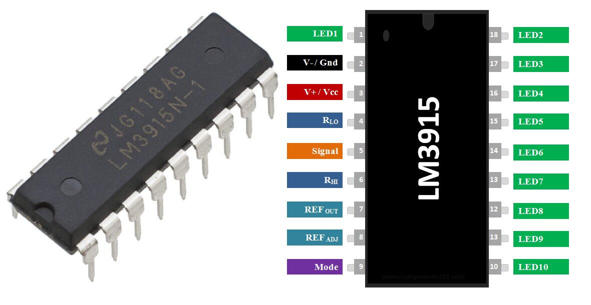
Pinout Description of LM3915:
- Pins 1 and 10 to 18 (LED1 to LED10): Control 10 LEDs.
- Pin 2 (V- / Ground): Connect to ground.
- Pin 3 (V+ / Vcc): Supply voltage (3V to 25V).
- Pin 4 (RLO): Low-level voltage for potential divider.
- Pin 5 (Signal): Analog signal input pin controlling the LEDs.
- Pin 6 (RHI): High-level voltage for potential divider.
- Pin 7 (REF OUT): Output reference voltage for LED current limiting.
- Pin 8 (REF ADJ): Adjusts the reference voltage.
- Pin 9 (Mode): Selects between dot/bar mode when set high or low.
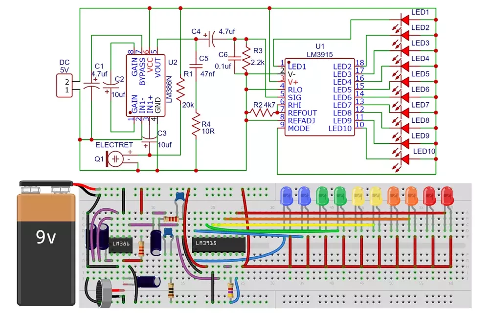
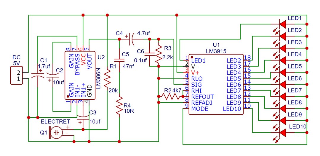
LM3915 VU Meter Circuit – Audio Spectrum Visualizer:
Components Required:
- LM3915 IC
- LM386 Audio IC
- Electret Microphone
- 10 LEDs (Red, orange, Yellow, Green, Blue all two)
- Resistors (4.7k, 2.2k, 10, 20k)
- Capacitors (2x 10uf, 4.7uf 1x 47nf, 0.1uf)
- Audio input source (e.g., microphone or line-in)
- Power supply (typically 5V to 9V)
- PCB Board
- Small Switch (if needed)
LM3915 VU Meter Circuit Working:
The LM3915-based VU meter is a simple yet effective way to visualize audio signals. Here’s how it works:
- Power Supply: The LM3915 operates within a voltage range of 3V to 25V. The power supply at the Vcc pin drives the IC and its operations.
- Input Signal: The input signal at pin 5 (SIG) can be an audio signal, varying light intensity, or a pulse signal. The audio signal’s amplitude can range from 1.2V to 12V.
- Setting Reference Voltage: Based on the audio signal’s voltage, set the reference voltage using resistors R1 and R2. For example, if the audio signal’s amplitude is 3.2V, RHI and REF OUT should be supplied with 3.2V, and RLO should be 0V. Using 1kΩ resistors for R1 and R2 would set it to 3.6V.
- Setting LED Current: The output current through the LEDs (I_LED) is set using a resistor divider network at pin 7 (REF OUT). You can adjust LED current by using a potentiometer between pin 7 and Ground.
Operating Modes:
The IC can operate in two modes:
- Bar Graph Mode: LEDs light up in a continuous bar.
- Dot Mode: At a time only one LED lights up.
Switching pin 9 high or low changes the mode. For a better visual experience, keep pin 9 high to use the dot mode.
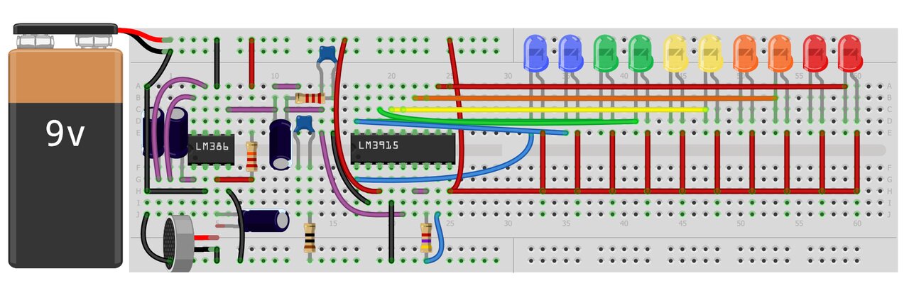
Building LM3915 VU Meter Circuit:
The circuit is simple to build with just a few passive components. Ensure the connections are accurate as per the circuit diagram and test the circuit with an audio signal. The LEDs should light up in response to the audio, displaying the signal strength.
Here we have used LM386 Audio amplifier IC to amplify microphone output signal.
When the audio signal is applied to pin 5 (SIG), the LM3915 will light up the LEDs in response to the signal’s amplitude.
The LM3915 provides a logarithmic display, meaning each LED represents a step in the audio signal level, with each step being a fixed decibel increase.
Notes:
- Ensure that the power supply voltage matches the requirements of the LM3915 and the LEDs.
- Adjust the resistor values to set the appropriate current and voltage for the LEDs.
Conclusion:
This basic circuit diagram and explanation should help you get started with building your own LED VU meter using the LM3915. Make sure to refer to the LM3915 datasheet for detailed specifications.
VU meter circuit is an easy and effective project for visualizing audio signals. I hope you find this guide helpful. comment down your questions or feedback. Enjoy building your VU meter!
What is a Sensor? Types of Sensors, Classification & Applications