LC filters are widely used frequency-selective circuits in electronics that utilize an inductor (L) and a capacitor (C) to allow certain frequency components to pass while blocking others. Unlike RC filters, LC filters rely on the interaction between inductive reactance and capacitive reactance, making them highly effective in radio frequency (RF), power electronics, and communication systems.
Filtering is essential in electronic circuits to eliminate unwanted frequencies, suppress electrical noise, smooth signals, and isolate useful frequency components. Without proper filtering, signals may become distorted, unstable, or contaminated with interference.
LC filters have been used extensively since the early development of radio transmitters and receivers, where selective frequency tuning was required. Even today, LC filters remain extremely important in high-frequency applications, switch-mode power supplies, RF communication circuits, and signal processing systems due to their high efficiency and low power loss.
Related Articles:
- Types of Filter Circuits: Working Principles, Formula & Applications
- Inductive Reactance and Capacitive Reactance Explained
- Passive RC Filters: Circuit Diagram, Types, Working & Applications
- RL Filters: Circuit Diagram, Working, Types, and Applications
Passive Components of LC Circuit
An LC filter is constructed using two passive energy-storage components:
- Inductor (L)
- Capacitor (C)
These components respond differently to varying signal frequencies, forming the basis of filtering action.
Inductor (L)
An inductor is a passive electrical component that stores energy in the form of a magnetic field when current flows through it.
The voltage across an inductor is given by:
V = L di/dt
Where:
- L = inductance (Henry)
- I = current (Ampere)
Inductors oppose changes in current and exhibit frequency-dependent reactance.
Inductive Reactance
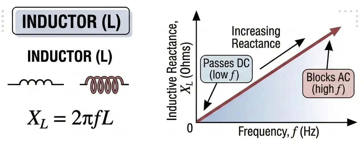
The opposition offered by an inductor to alternating current is called inductive reactance, given by:
XL = 2πfL
Where:
- f = frequency (Hz)
- L = inductance (H)
As frequency increases, inductive reactance increases, making inductors more effective at blocking high-frequency signals.
Capacitor (C)
A capacitor stores electrical energy in the form of an electric field between two conductive plates separated by a dielectric material.
The charge stored in a capacitor is:
Q = CV
Where:
- C = capacitance (Farad)
- V = voltage (Volt)
Capacitors oppose rapid changes in voltage and allow higher frequency signals to pass more easily.
Capacitive Reactance
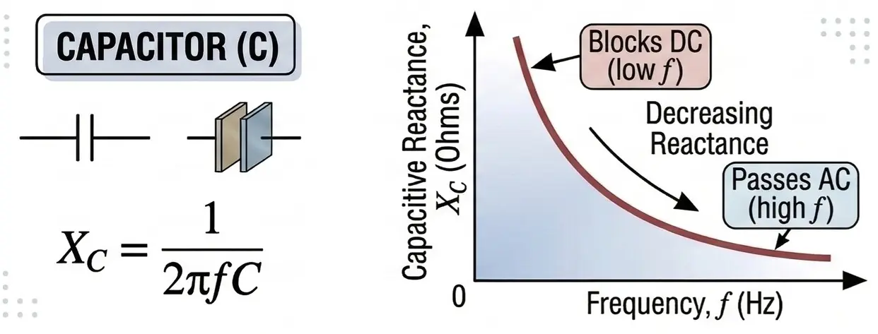
The opposition offered by a capacitor to alternating current is called capacitive reactance, given by:
XC = 1 / (2πfC)
Where:
- f = frequency (Hz)
- C = capacitance (F)
As frequency increases, capacitive reactance decreases.
Frequency Domain Concept
LC filters operate based on the frequency-dependent impedance of inductors and capacitors.
- Inductors block high frequencies
- Capacitors block low frequencies
By combining these two components, LC filters can be designed to selectively pass or reject specific frequency ranges.
This behavior is best analyzed using frequency domain analysis, where the signal response is studied as a function of frequency.
What Is an LC Filter?
An LC filter is a passive filter composed of an inductor and a capacitor arranged to control the frequency response of electrical signals.
- LC filters are commonly used when:
- High efficiency is required
- High-frequency filtering is needed
- Minimal signal power loss is desired
Passive vs Active Filters
- Passive Filters
- Use only resistors, inductors, and capacitors
- Do not require external power
- Cannot provide amplification
- Active Filters
- Use operational amplifiers along with passive components
- Require external power
- Can provide signal gain
LC filters are classified as second-order filters because they contain two energy-storage elements, resulting in a roll-off rate of 40 dB per decade, which is steeper than RC filters.
Resonance in LC Filters
An LC filter consists of an inductor (L) and a capacitor (C). These components store energy in magnetic and electric fields and exchange energy between them. This interaction creates resonance at a specific frequency.
At resonance, the inductive reactance equals the capacitive reactance.
XL = XC
Where:
- XL = 2πfL
- XC = 1 / (2πfC)
Effects at Resonance
- Net reactance becomes zero
- Current becomes maximum in a series circuit
- Voltage across L or C may become very large
- Energy oscillates between the inductor and capacitor
- Maximum energy transfer occurs
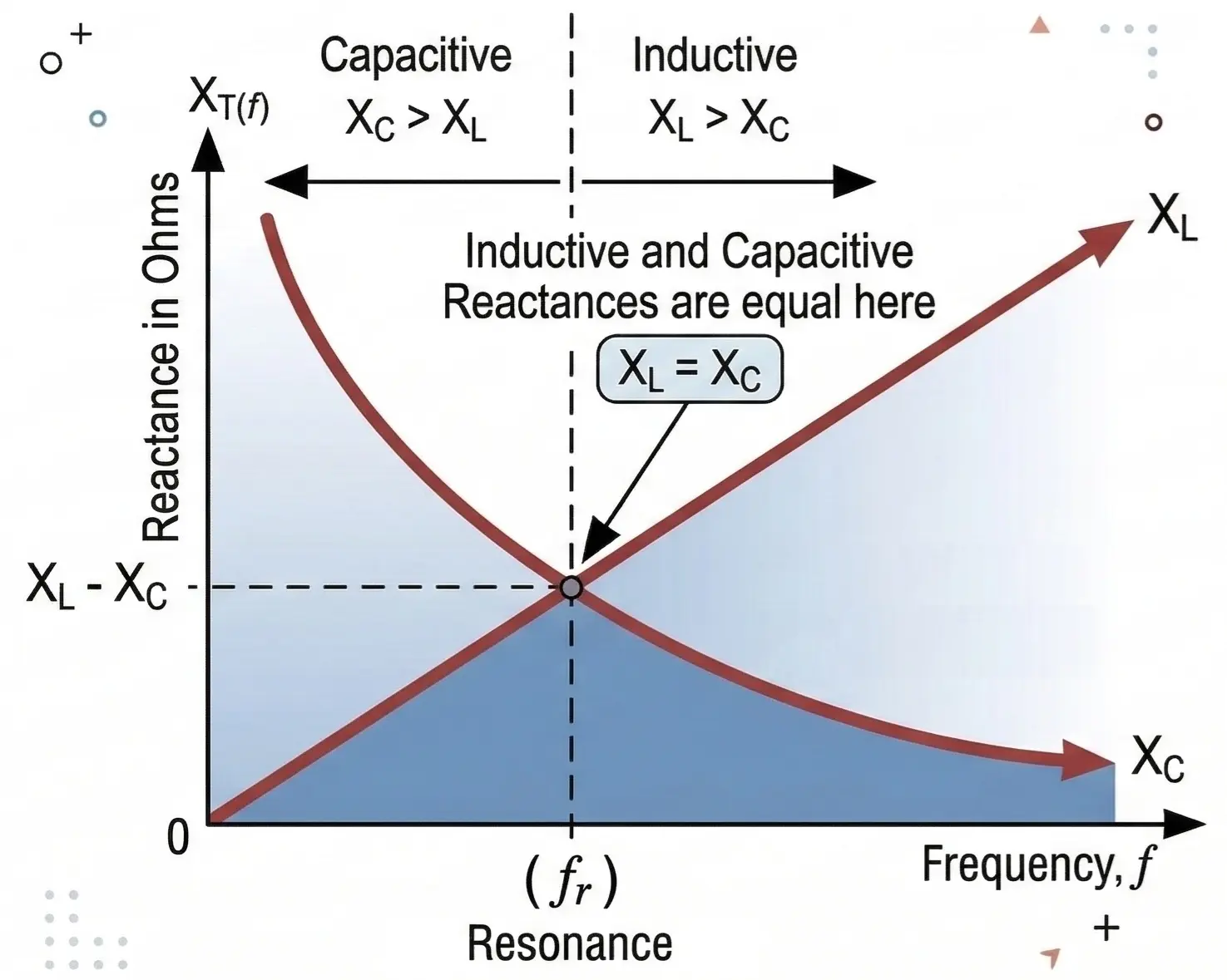
Resonant Frequency
The resonant frequency of an LC circuit is:
f₀ = 1/(2π√(LC))
- f₀ = Resonant frequency (Hz)
- L = Inductance (Henries)
- C = Capacitance (Farads)
At the resonant frequency, the inductive and capacitive reactance become equal.
Quality Factor (Q)
The Quality Factor (Q) indicates how sharp or selective the resonance of a circuit is.
Q = f₀ / Bandwidth
- High Q: Sharp resonance and narrow bandwidth
- Low Q: Wide bandwidth and less selective filtering
High-Q circuits store energy efficiently and lose less energy during each oscillation cycle.
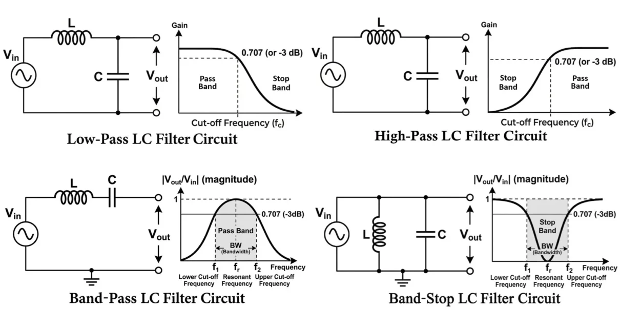
Bandwidth
Bandwidth is the range of frequencies that the filter allows to pass effectively.
Bandwidth (BW) = f₂ − f₁
- f₁ = Lower cutoff frequency
- f₂ = Upper cutoff frequency
These cutoff frequencies occur at the −3 dB points where the output power drops to half of its maximum value.
Selectivity
Selectivity refers to the ability of the filter to separate the desired frequency from nearby unwanted frequencies. It is directly related to the Q factor.
- High Q → High selectivity
- Low Q → Low selectivity
Example: In a radio receiver, the filter must select one station frequency while rejecting nearby stations.
- Resonant Frequency: Frequency where XL = XC
- Quality Factor (Q): Indicates sharpness of resonance
- Bandwidth: Frequency range the filter passes
- Selectivity: Ability to reject nearby frequencies
High Q results in narrow bandwidth and higher selectivity.
Frequency Response of LC Filters
LC filters exhibit sharper frequency response than RC filters.
- Low-Pass LC Filter
- Low frequencies pass with minimal attenuation
- Output begins decreasing after cutoff frequency
- Roll-off rate is −40 dB/decade
- High-Pass LC Filter
- Low frequencies are attenuated
- Signal begins increasing near cutoff frequency
- High frequencies pass with minimal loss
Types of LC Filters
LC filters can be configured in multiple ways depending on how the inductor (L) and capacitor (C) are connected in the circuit. These configurations affect the impedance characteristics, filtering performance, and suitability for different applications. The four fundamental types of LC filters are Low-Pass, High-Pass, Band-Pass, and Band-Stop filters.
LC filters can be configured in several ways depending on the required frequency response. The most common types are:
- Low-Pass LC Filter
- High-Pass LC Filter
- Band-Pass LC Filter
- Band-Stop LC Filter
The most common LC filter designs are:
- L-type filters
- π (Pi) filters
- T-type filters
Each of these structures can be used to implement low-pass, high-pass, band-pass, or band-stop filters depending on the arrangement inductive reactance (XL) and capacitive reactance (XC), which vary with frequency.
Because these reactances change in opposite ways with frequency, LC networks can be designed to control signal transmission over specific frequency ranges.
LC Placement Rule for Impedance Matching
In impedance-matching networks (such as an L-section network), the placement of reactive components follows a simple guideline:
- Low-impedance side (ZL) → Inductor
- High-impedance side (ZH) → Capacitor
An inductor is placed near the low-impedance side because it opposes changes in current and helps raise the effective impedance seen by the source. A capacitor is placed near the high-impedance side because it provides a low-reactance path for AC signals, helping reduce the effective impedance.
This arrangement enables the network to transform one resistance into another while maintaining maximum power transfer and stable circuit operation.
LC Low-Pass Filter (LPF)
An LC Low-Pass Filter allows signals with frequencies below a certain cutoff frequency to pass while attenuating higher-frequency components.

Circuit Configuration
The typical LC low-pass filter consists of:
- Inductor connected in series with the input
- Capacitor connected in parallel with the output
Working Principle
The operation of the LC low-pass filter depends on the frequency response of both components.
- At low frequencies:
- Inductive reactance is very small.
- Capacitive reactance is very large.
- The signal passes easily through the inductor to the output.
- At high frequencies:
- Inductive reactance increases significantly.
- Capacitive reactance becomes small.
- The capacitor provides a low-impedance path to ground, diverting high-frequency signals away from the load.
Thus, low-frequency signals appear at the output while high-frequency signals are suppressed. The cutoff frequency of an LC low-pass filter is same as resonance frequency.
Applications
- Power supply ripple filtering
- Switch-mode power supplies (SMPS)
- Audio signal smoothing
- RF signal conditioning
Low-Pass LC Filter Configurations
Low-pass LC filters allow low-frequency signals to pass while attenuating high-frequency signals. They are widely used in power supply ripple filtering, audio systems, and RF circuits.
L-Type Low-Pass LC Filter
This is the simplest LC filter configuration.
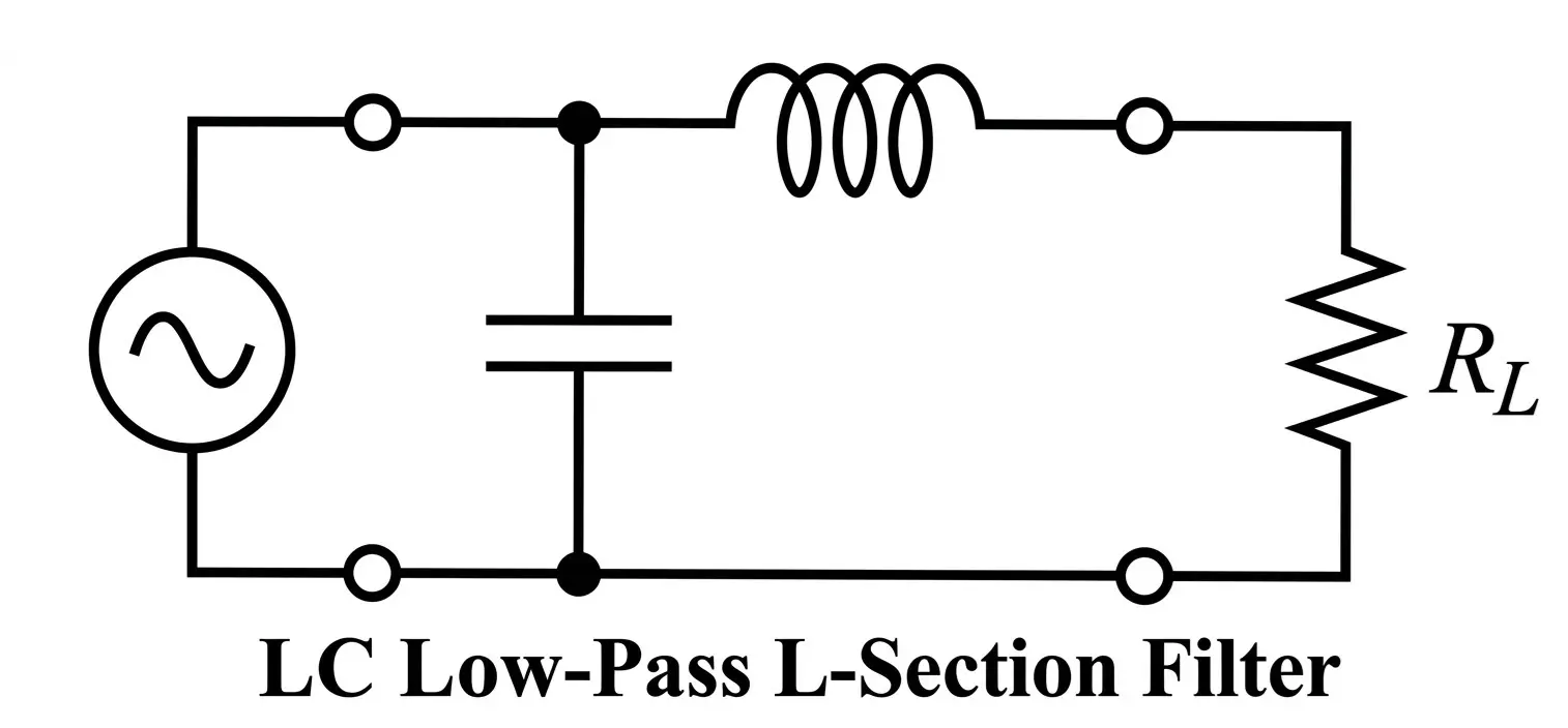
- Series Inductor → Shunt Capacitor
- Input ZL → L → C → Output ZH
- Input ZH → C → L → Output ZL
Working
- At low frequencies, inductive reactance is small and capacitive reactance is large, so the signal passes to the output.
- At high frequencies, inductive reactance increases while capacitive reactance decreases, causing high-frequency components to be shunted to ground.
This configuration is commonly used in switch-mode power supplies and DC output filters.
π (Pi) Low-Pass LC Filter
The π filter consists of two capacitors and one inductor, forming a structure that resembles the Greek letter π.
Circuit

- Shunt Capacitor → Series Inductor → Shunt Capacitor
- Input ZH → C → L → C → Output ZH
Working
- The first capacitor reduces incoming high-frequency noise.
- The inductor blocks high-frequency currents.
- The second capacitor further smooths the output signal.
This configuration provides better ripple suppression than a simple L filter and is widely used in power supply filtering circuits.
T-Type Low-Pass LC Filter
The T filter consists of two inductors and one capacitor arranged in a T configuration.
Circuit Structure
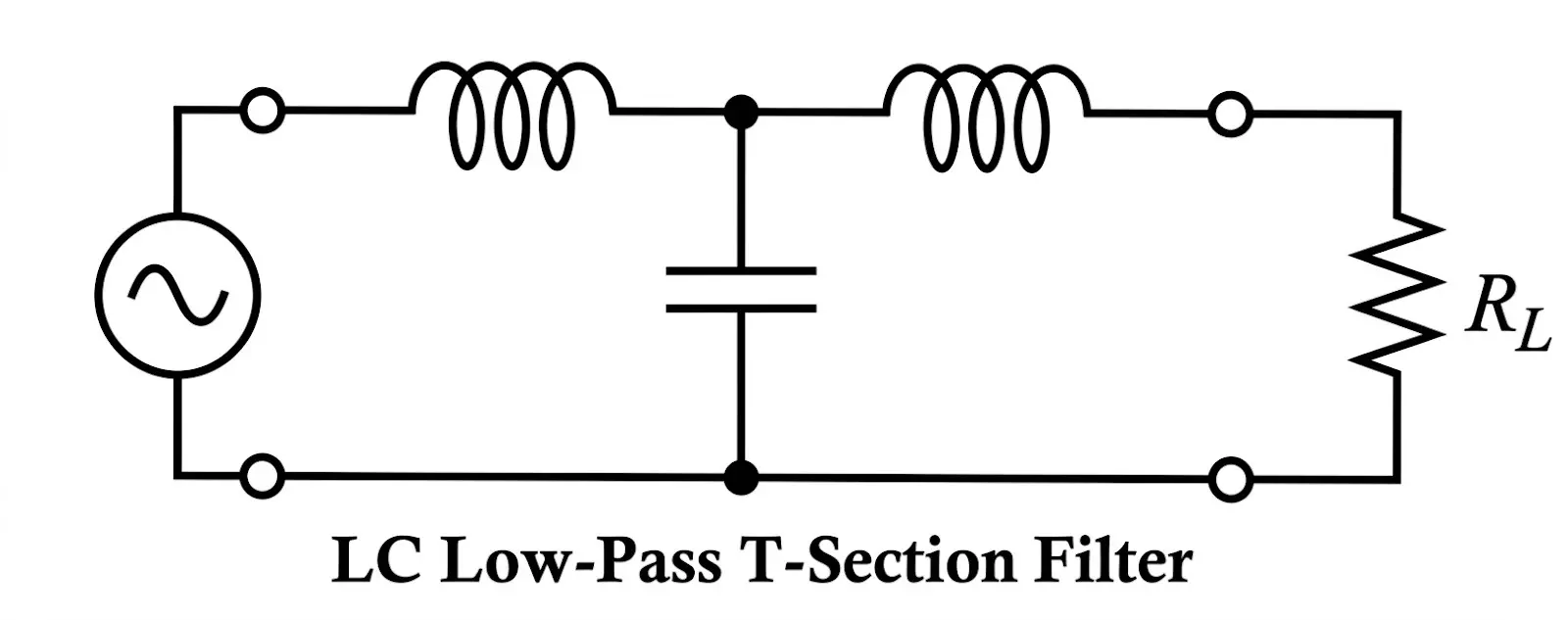
- Series Inductor → Shunt Capacitor → Series Inductor
- Input ZL → L → C → L → Output ZL
Working
- The two inductors block high-frequency components.
- The capacitor shunts unwanted frequencies to ground.
- This configuration provides improved attenuation and impedance matching.
T filters are often used in communication circuits and RF filtering networks.
LC High-Pass Filter (HPF)
An LC High-Pass Filter allows signals with frequencies above the cutoff frequency to pass while attenuating lower-frequency components.
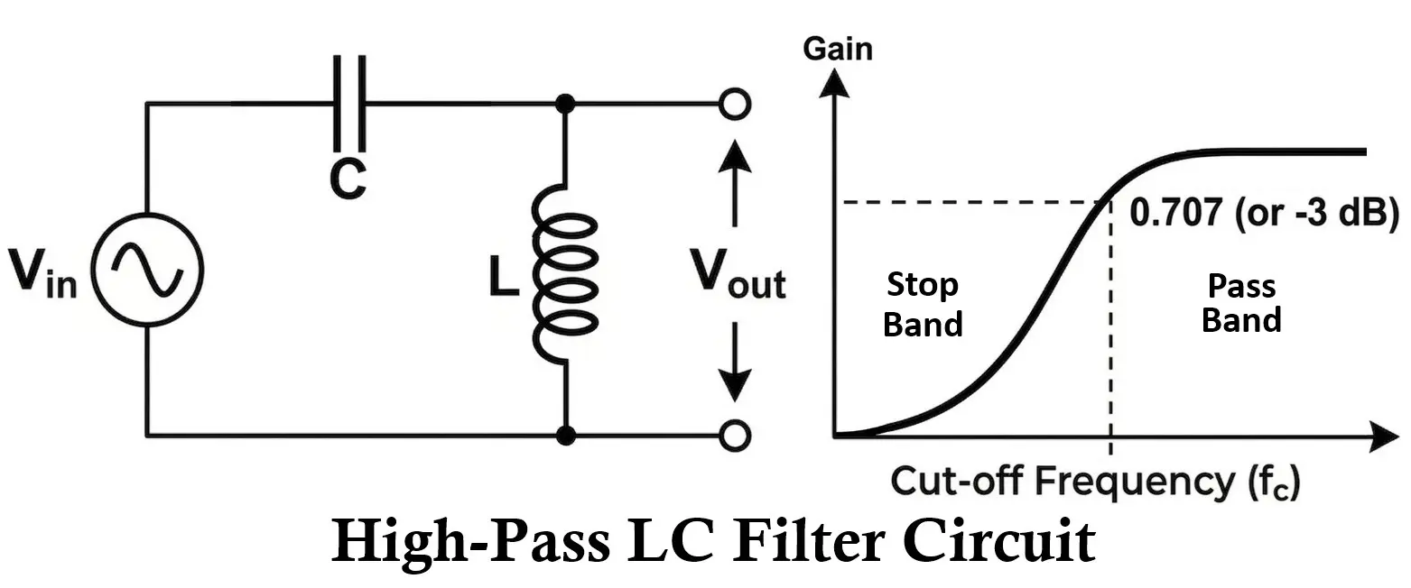
Circuit Configuration
A typical LC high-pass filter consists of:
- Capacitor connected in series with the input
- Inductor connected in parallel with the load
Working Principle
- At low frequencies:
- Capacitive reactance is very high.
- The capacitor blocks low-frequency signals.
- The output voltage becomes very small.
- At high frequencies:
- Capacitive reactance becomes small.
- Signals pass easily through the capacitor.
- The inductor presents high reactance, preventing high-frequency signals from flowing to ground.
As a result, high-frequency signals appear at the output while low-frequency signals are attenuated.
Applications
- RF signal coupling
- Audio crossover circuits
- Removing low-frequency noise
- Communication systems
High-Pass LC Filter Configurations
High-pass LC filters allow high-frequency signals to pass while blocking low-frequency components.
L-Type High-Pass LC Filter

- Shunt Inductor → Series Capacitor
- Input ZL → L → C → Output ZH
- Input ZH → C → L → Output ZL
Working
- At low frequencies, capacitive reactance is high and blocks the signal.
- At high frequencies, capacitive reactance decreases, allowing the signal to pass.
- The inductor provides a path for low-frequency signals to ground.
This configuration is commonly used in RF circuits and coupling networks.
π High-Pass LC Filter

- Shunt Inductor → Series Capacitor → Shunt Inductor
- Input ZL → L → C → L → Output ZL
Working
- The inductors block low-frequency signals.
- The capacitor allows high-frequency signals to pass.
- Provides improved high-frequency response compared to simple LC networks.
This design is frequently used in RF signal processing circuits.
T-Type High-Pass LC Filter

- Series Capacitor → Shunt Inductor → Series Capacitor
- Input ZH → C → L → C → Output ZH
Working
- The capacitors pass high-frequency signals.
- The inductor blocks low-frequency components.
- Offers better impedance characteristics than simple L filters.
T high-pass filters are used in antenna coupling and communication systems.
LC Band-Pass Filter (BPF)
A Band-Pass LC Filter allows signals within a specific range of frequencies to pass while rejecting frequencies outside this range.
Circuit Configuration
A band-pass filter is typically formed by combining:
- A series resonant circuit: Passes frequencies near fr.
- A parallel resonant circuit: Attenuates frequencies above and below it.
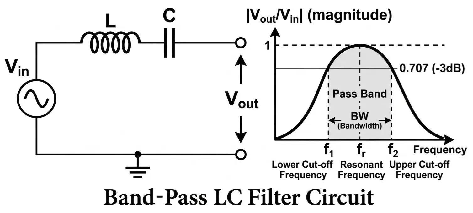
The most common configuration uses a series LC network connected in the signal path.
Input → Series LC Network → Output
Working Principle
- At resonant frequency:
- Inductive reactance equals capacitive reactance.
- The impedance of the series LC circuit becomes minimal.
- Maximum signal passes through the circuit.
- At frequencies below resonance:
- Capacitive reactance dominates.
- Signal transmission decreases.
- At frequencies above resonance:
- Inductive reactance dominates.
- Signal transmission again decreases.
Thus, only a specific band of frequencies around the resonant frequency passes through the filter. Bandwidth determines how wide the passband is and depends on circuit resistance and component values.
Applications
- Radio receivers for channel selection
- Wireless communication systems
- Signal processing circuits
- Frequency-selective amplifiers
Band-Pass LC Filter Configurations
Band-pass filters allow a specific range of frequencies to pass while attenuating frequencies below and above that range. They are widely used in communication systems, RF circuits, and signal processing.
Series Resonant Band-Pass Filter
- Series LC connected in the signal path
- Input → L – C → Output
Working
- At the resonant frequency, inductive reactance equals capacitive reactance
- The circuit impedance becomes minimum
- The desired frequency passes easily through the circuit
- Frequencies above and below resonance experience higher impedance and are attenuated
Commonly used in RF tuning circuits and frequency selection stages.
Parallel Resonant Band-Pass Filter
- Parallel LC connected in the signal path
- Input → L || C → Output
Working
- At the resonant frequency, the parallel LC circuit presents very high impedance
- The signal is not shunted away, so the resonant frequency appears at the output
- Frequencies outside the resonant band are partially bypassed or attenuated
Widely used in radio receivers, oscillators, and RF amplifiers for frequency selection
LC Band-Stop Filter (Notch Filter)
A Band-Stop LC Filter blocks signals within a specific frequency range while allowing frequencies outside this range to pass.
It is often referred to as a notch filter when the rejected band is narrow.
Circuit Configuration
A band-stop filter is usually formed using a parallel resonant LC circuit connected in the signal path.
Input → Parallel LC Network → Output

Working Principle
- At resonant frequency:
- Inductive reactance equals capacitive reactance.
- The impedance of the parallel LC circuit becomes very high.
- Signal transmission is greatly reduced.
- At frequencies below resonance:
- Capacitive reactance dominates.
- Signals pass through.
- At frequencies above resonance:
- Inductive reactance dominates.
- Signals also pass through.
Thus, the filter rejects only a narrow band around the resonant frequency while allowing other frequencies to pass.
Applications
- Removing interference in communication systems
- Eliminating power-line hum (50/60 Hz)
- Noise suppression circuits
- Audio signal processing
Band-Stop LC Filter Configurations
Band-stop filters reject a specific band of frequencies while allowing others to pass. They are commonly used to remove interference or unwanted signals.
Parallel Resonant Notch Filter
- Parallel LC connected across the signal line.
- Input → L || C → Output
Working
- At resonant frequency, the parallel LC circuit presents very low impedance.
- The unwanted frequency is shunted to ground.
- Other frequencies pass through the circuit.
This configuration is used for noise elimination and harmonic suppression.
Series Resonant Band-Stop Filter
- Series LC connected in the signal path.
- Input → L – C → Output
Working
- At resonance, impedance becomes extremely low.
- The signal is strongly attenuated at that frequency.
- Frequencies outside the stop band pass normally.
These filters are commonly used in communication systems and EMI suppression circuits.
Comparison of LC Filter Types
| Filter Type | Passes | Blocks | Typical Use |
|---|---|---|---|
| Low-Pass | Low frequencies | High frequencies | Power supply filtering |
| High-Pass | High frequencies | Low frequencies | Audio crossover networks |
| Band-Pass | Specific frequency band | Frequencies outside band | Radio tuning circuits |
| Band-Stop | All except certain band | Specific frequency band | Noise elimination |
Configurations of LC Filters

| Filter Type | Common Circuit Forms |
|---|---|
| Low-Pass LC | L-section, π-section, T-section |
| High-Pass LC | L-section, π-section, T-section |
| Band-Pass LC | Series resonant, Parallel resonant |
| Band-Stop LC | Parallel resonant notch, Series resonant notch |
Design Procedure for LC Filter
- Specify the required cutoff or resonant frequency.
- Select a convenient capacitor value.
- Calculate the required inductance using:
L = 1 / ((2πf)²C)
- Choose standard component values.
- Verify performance using frequency response analysis.
Practical Considerations
- Inductor resistance causes power loss
- Parasitic capacitance and inductance affect high-frequency response
- Component tolerances change resonant frequency
- Core saturation limits inductor performance
- Physical size of inductors may be large in low-frequency filters
Advantages of LC Filters
- High efficiency with minimal power loss
- Suitable for high-frequency applications
- Sharper frequency response than RC filters
- Capable of handling high power levels
- Widely used in RF and power electronics
- Lower signal attenuation in passband
Disadvantages of LC Filters
- Inductors can be bulky and expensive
- Inductor cores may saturate at high currents
- Magnetic interference may occur
- Design becomes complex at low frequencies
- Component tolerances affect resonance accuracy
Applications of LC Filters
- Radio transmitters and receivers
- RF communication circuits
- Antenna matching networks
- Switch-mode power supplies
- Audio crossover networks
- Signal conditioning circuits
- Power supply ripple filtering
- EMI suppression circuits
RC vs RL vs LC vs RLC Comparison
| Parameter | RC Filter | RL Filter | LC Filter | RLC Filter |
|---|---|---|---|---|
| Components | Resistor + Capacitor | Resistor + Inductor | Inductor + Capacitor | Resistor + Inductor + Capacitor |
| Order | First-order | First-order | Second-order | Second-order (can be higher) |
| Roll-off rate | 20 dB/decade | 20 dB/decade | 40 dB/decade | 40 dB/decade (or higher depending on design) |
| Power efficiency | Lower | Moderate | Higher | Moderate to high |
| Frequency range | Low to medium frequency | Low to medium frequency | High frequency | Wide range (audio to RF depending on design) |
| Size | Compact | Inductor may increase size | Inductors may be bulky | Larger due to multiple components |
| Typical applications | Audio filtering, signal smoothing | Current filtering, power circuits | RF filtering, power supply filtering | Tuned circuits, band-pass filters, communication systems |
Conclusion
LC filters are powerful passive filtering circuits that use inductors and capacitors to control the frequency content of electrical signals. Due to their high efficiency, low power loss, and sharp frequency selectivity, they are widely used in RF communication systems, power electronics, and signal processing circuits.
Although LC filters require inductors, which may increase size and cost, their superior filtering performance makes them essential in many high-frequency applications where RC filters are not sufficient.
Types of Filter Circuits: Working Principles, Formula & Applications
RC Filters: Circuit Diagram, Working, Types and Applications
RL Filters: Circuit Diagram, Working, Types, and Applications
