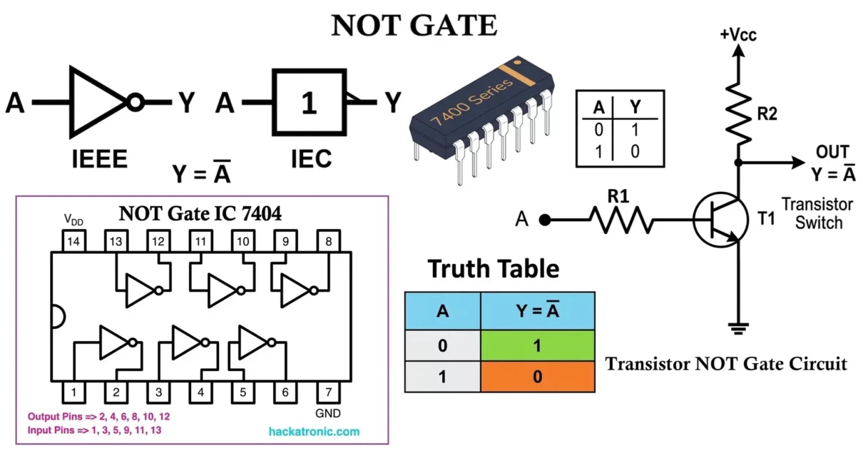
A NOT Gate is one of the most fundamental and simplest building blocks in digital electronics. It is a type of logic gate that performs a basic Boolean operation known as logical inversion. In simple terms, a NOT gate produces an output that is the opposite (complement) of its input. If the input is HIGH […]
Electronic components
OR Gate: Symbol, Truth Table, Logic Circuit, and IC Numbers
An OR Gate is one of the most fundamental building blocks in digital electronics. It is a type of logic gate that performs a basic Boolean operation known as logical addition. In simple terms, an OR gate produces an output when any one or more of its inputs are HIGH (1). The output becomes LOW […]
AND Gate: Symbol, Truth Table, Logic Circuit, and IC Numbers
An AND Gate is one of the most fundamental building blocks in digital electronics. It is a type of logic gate that performs a basic Boolean operation known as logical multiplication. In simple terms, an AND gate produces an output only when all of its inputs are HIGH (1). If any input is LOW (0), […]
LC Filters: Circuit Diagram, Working, Types, and Applications
LC filters are widely used frequency-selective circuits in electronics that utilize an inductor (L) and a capacitor (C) to allow certain frequency components to pass while blocking others. Unlike RC filters, LC filters rely on the interaction between inductive reactance and capacitive reactance, making them highly effective in radio frequency (RF), power electronics, and communication […]
Inductive Reactance and Capacitive Reactance Explained
Understanding inductive reactance (XL) and capacitive reactance (XC) is essential for analyzing AC circuits, designing filters, oscillators, power electronics systems, and communication circuits. This article explains all fundamental concepts including resistance, reactance, impedance, frequency response, graphs, ideal and real component behavior, solved examples, advantages, disadvantages, and applications. In electronic circuits, especially those operating with alternating […]
RL Filters: Circuit Diagram, Working, Types, and Applications
RL Filter Circuit is a fundamental passive filtering circuits that use a resistor (R) and an inductor (L) to control signal frequency. Like RC filters, RL filters are first-order filters, but instead of capacitive reactance, they rely on inductive reactance, which increases with frequency. Because of their simple structure and predictable frequency behavior, RL filters […]


