So, let’s make a simple homemade inverter it is just a fun project which can power a 50W to 100W light bulb or a small table fan which may create noise due to impure and non-sinusoidal AC input. This circuit can’t compete with any of the inverters available in the market.
Also, watch this video 12V to 240V Power Inverter
Here is the simple power inverter circuit diagram using IC CD4047 and MOSFET irf540. IC CD4047 is a monostable/astable multivibrator.
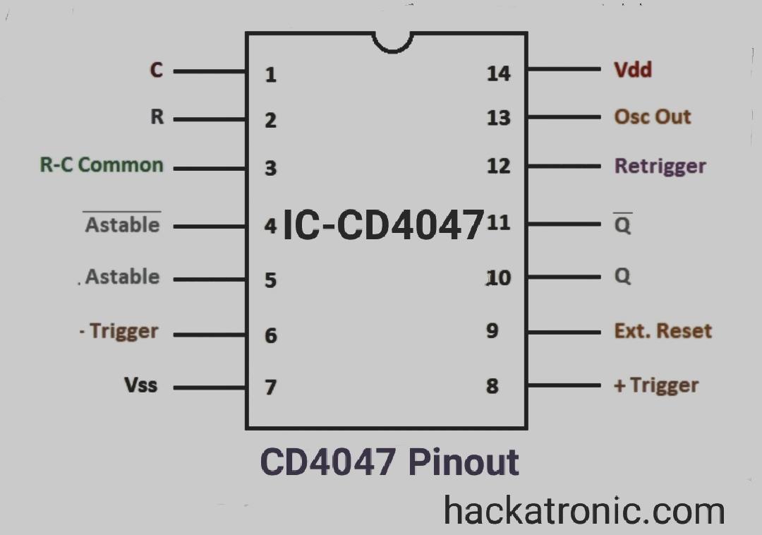
IC CD4047:
CD4047 is a 14-pin IC, It’s a low-power CMOS logic based multivibrator circuit IC. It can operate in the monostable mode or astable mode. This IC is easy to use for both modes and requires less external components to operate. It has a voltage range of 3V-15V and works best at 5V DC supply.
Now the question arises here Why IC CD4047 is being used here?
The answer is that We have to drive the gates of MOSFET. So this task is done by CD4047 by generating square wave or PWM. Most of the power inverter uses this technique to drive the MOSFETs or transistors.
Circuit Diagram for CD4047 Inverter:
Click the image to enlarge.
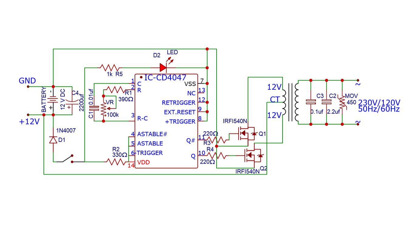 The circuit is simple, IC CD4047 drives the two MOSFETs which are in push-pull configuration. As the usual transformer cannot work on DC, so we have to make voltage and current changing w.r.t time. So, the flux will be induced in the core which will induce a voltage on the secondary winding. You can adjust the potentiometer to get the desired frequency. Usually, the frequency is 50 or 60 Hz.
The rating of the transformer should be enough to bear the output power.
Battery should be greater than 10Ah so that battery voltage should not drop, and it should work for a long time. The LED here indicates that the power inverter is ON. So, whenever it is ON, don’t touch the inverter otherwise you will get harmed.
Components:
- IC – CD4047
- TR1 Center tapped Transformer (12V to 230V)
- R1 390 ohm (1/4watt)
- R2 330 (1/4watt)
- R5 1k (1/4watt)
- R3, R4 220 ohm (1/4watt)
- VR 100k variable resistor
- C1 0.01uF
- C2 2.2uF (450v)
- C3 0.1uF(450v)
- C4 2200uF (25V)
- D1 1N4007
- D2 LED (green red or any color)
- Q1, Q2 IRF540 (100V, 33A & 140W)
Working of Inverter using IC CD4047
In the above circuit, the battery provides 12v DC and enough current. IC CD4047 works in the astable mode it continuously changes output at pin no 10 and 11 thus giving a square wave output they are opposite to each other.
These two output pins are connected to the gate of the two MOSFETs which are arranged in push-pull configuration. So at a time, only one transistor is on. These transistors can handle a very high current through them.
The source of both the MOSFETs is connected to the ground and the drain is connected to the two ends of the secondary winding of the transformer. The center taped wire is connected to +12VCC.
when the first MOSFET Q1 is on the current path is { +ve terminal => transformer => transistor Q1 => -ve terminal of battery}, and when MOSFET Q2 is on the current path is { +ve terminal => transformer => transistor Q2 => -ve terminal of battery}.
By this method, an alternating current(AC) is produced in the secondary winding (having less number of turns) of the transformer. This alternating current induces a High Voltage AC in the primary(having more number of turns) winding of the transformer. This induced current is not sinusoidal, it is an alternating square wave. this current can easily run 100W bulb a small table fan and some other non-sensitive electronic devices.
Some Important precautions with CD4047 Inverter circuit:
Good quality and large heat sinks must be attached with MOSFETs. These MOSFETs will get hot while working. So, to avoid damage due to overheating, heatsinks should be used.
Be careful while working with this circuit due to its high voltage (230V).
To charge the battery, you can refer to this article Automatic 12V Battery Charger. There is a need for some relays to attach the battery charger circuit. If AC main is not present, the power inverter should be ON otherwise battery should be in charging mode.
Why this circuit is not good or reliable?
The circuit made in this project is good for powering a light bulb small fan and some other insensitive devices. But it is not a reliable solution because of the following reasons
- The output is not sinusoidal in nature hence can’t be used for sensitive loads
- The output voltage is directly dependent on the input voltage.
- A small change in input side voltage may affect largely on the output voltage
- The input battery voltage may fluctuate or may get imbalanced if an unbalanced load is applied.
- This circuit does not have a feedback loop which becomes a big problem if there was a feedback loop the output could be controlled easily.
- Also, the load affects the frequency of the astable multivibrator.
if you have any query related to this circuit, feel free to ask.
Google Assistant Based Home Automation System ESP32, Blynk & IFTTT

what is the function of diode 1n4007? please
I made this circuit diagram project, but it’s not working😭.
Plz what is the need of the diode in the mosfet??. Plz help me…
Diode is the internal protection diode for MOSFET