RL Filter Circuit is a fundamental passive filtering circuits that use a resistor (R) and an inductor (L) to control signal frequency. Like RC filters, RL filters are first-order filters, but instead of capacitive reactance, they rely on inductive reactance, which increases with frequency.
Because of their simple structure and predictable frequency behavior, RL filters are widely used in power electronics, audio circuits, RF systems, and signal conditioning applications.
Filtering is essential in electronic systems to:
- Remove unwanted high-frequency noise
- Smooth pulsating DC waveforms
- Isolate desired signal bands
- Protect sensitive circuits from switching transients
Without filtering, electronic circuits would be vulnerable to distortion, instability, and noise contamination.
RL filters became especially important in power electronics and motor control systems, where inductors are commonly used for current smoothing and ripple reduction. Even today, RL filters remain relevant in power supplies, audio systems, RF networks and transient suppression circuits.
Passive Components of RL Circuit
Resistor (R)
A resistor limits current and follows Ohm’s Law:
V = IR
It dissipates power as heat and is ideally frequency independent.
Inductor (L)
An inductor stores energy in the form of a magnetic field when current flows through it.
The voltage-current relationship is:
V = L di/dt
Where:
- L = Inductance (Henry)
- di/dt = Rate of change of current
Unlike resistors, inductors behavior strongly depends on frequency.
Inductive Reactance
The opposition offered by an inductor to AC is called inductive reactance XL:
XL = 2πfL
Where:
- f = Frequency (Hz)
- L = Inductance (H)
Key behavior:
- At low frequency → XL is small
- At high frequency → XL is large
This increasing reactance with frequency forms the basis of RL filtering.
What is an RL Filter?
An RL filter is a first-order passive filter composed of one resistor and one inductor arranged to allow or reject signals based on frequency.
Since it contains only one energy storage element (inductor), it provides:
- Roll-off rate = 20 dB per decade
- Phase shift up to ±90°
Passive vs Active Filters:
- Passive filters use only R, L, and C components and do not require an external power supply.
- Active filters use active devices such as operational amplifiers along with passive components.
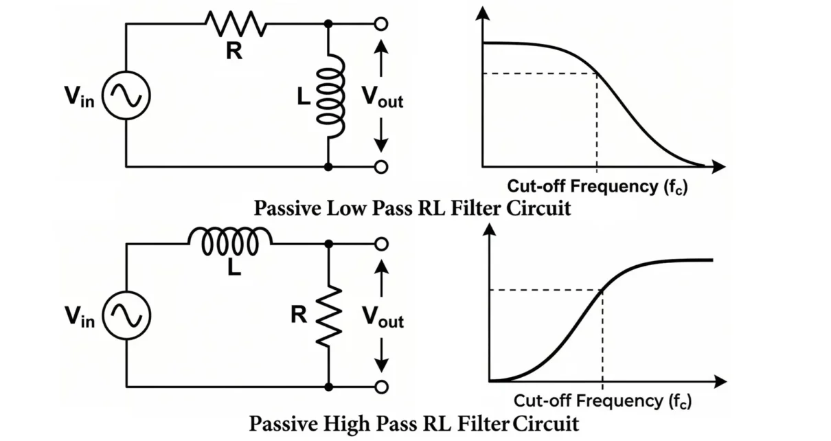
Types of RL Filters
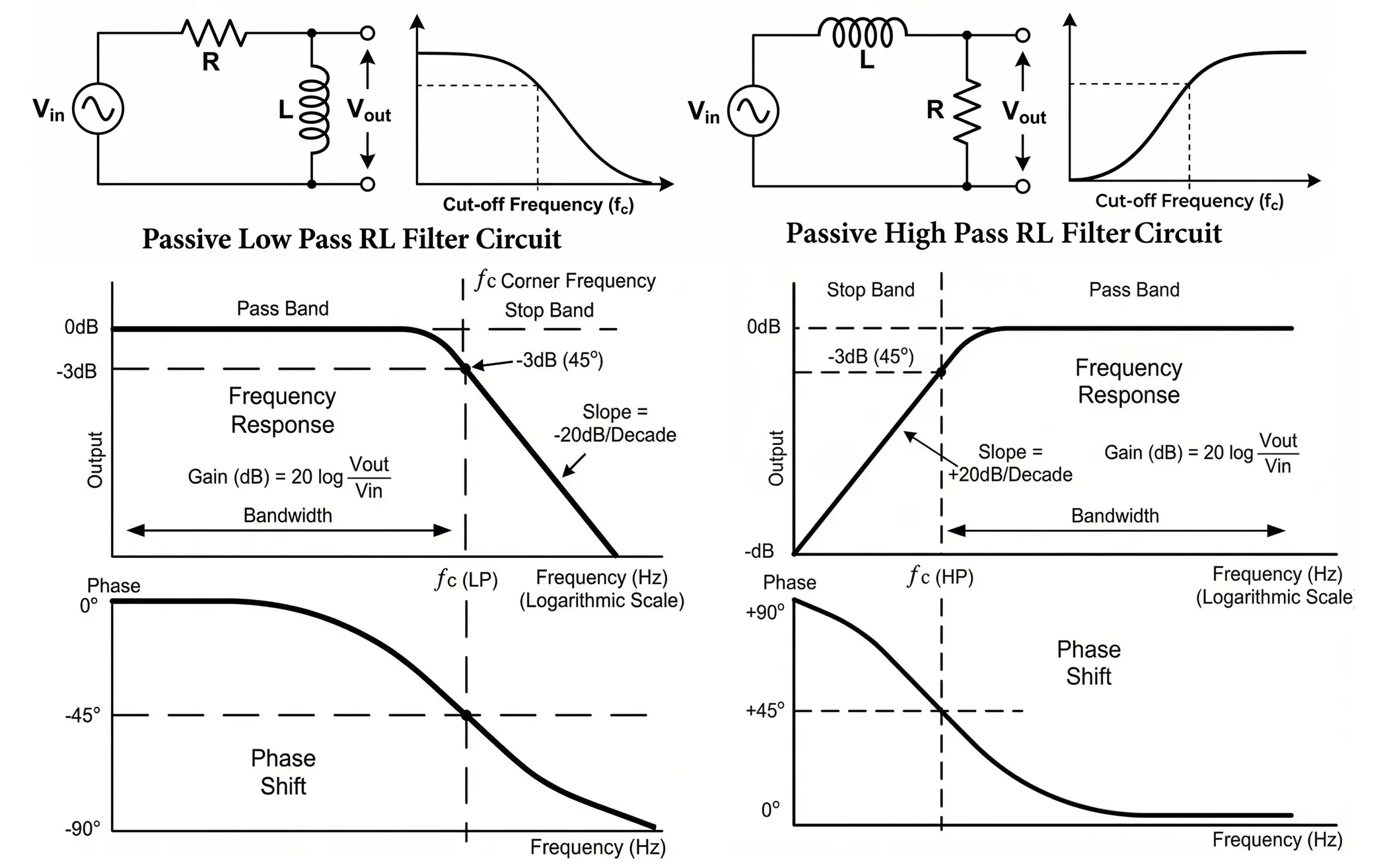
Low-Pass RL Filter Circuit
Low-Pass RL Filter is a series RL circuit where the output is taken across the resistor, allowing low frequencies to pass while attenuating high frequencies.
Circuit Diagram:
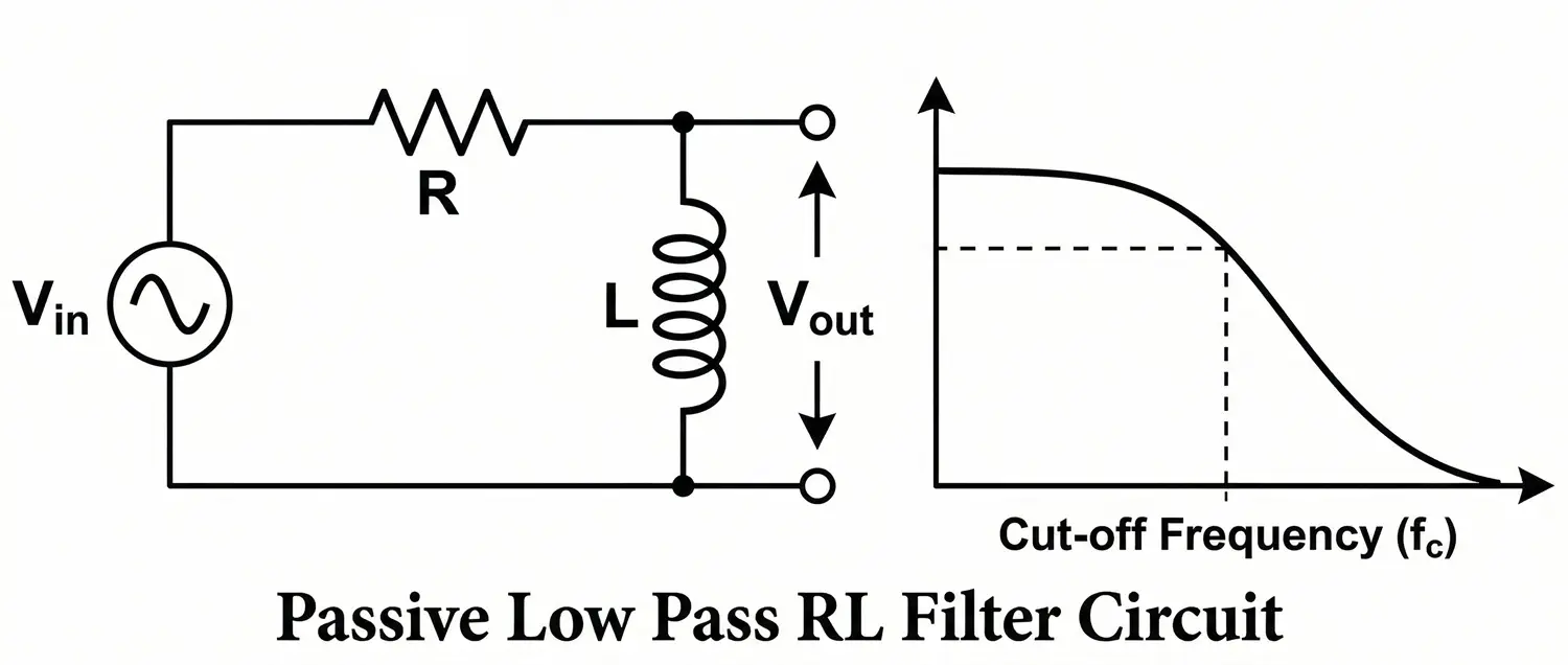
A low-pass RL filter consists of:
- Inductor in series with input
- Resistor connected to ground
- Output taken across the resistor
Working Principle:
- At low frequencies: XL is small → inductor behaves like short circuit → output ≈ input
- At high frequencies: XL is large → inductor blocks signal → output decreases
Thus, low frequencies pass, high frequencies are attenuated.
Transfer Function:
H(s) = R / (R + sL)
Cutoff Frequency:
fc = R / 2πL
Phase Response:
- 0° at low frequency
- −45° at cutoff
- −90° at high frequency
High-Pass RL Filter Circuit
High-Pass Filter is a series RL circuit where the output is taken across the inductor, allowing high frequencies to pass while attenuating low frequencies.
Circuit Diagram:
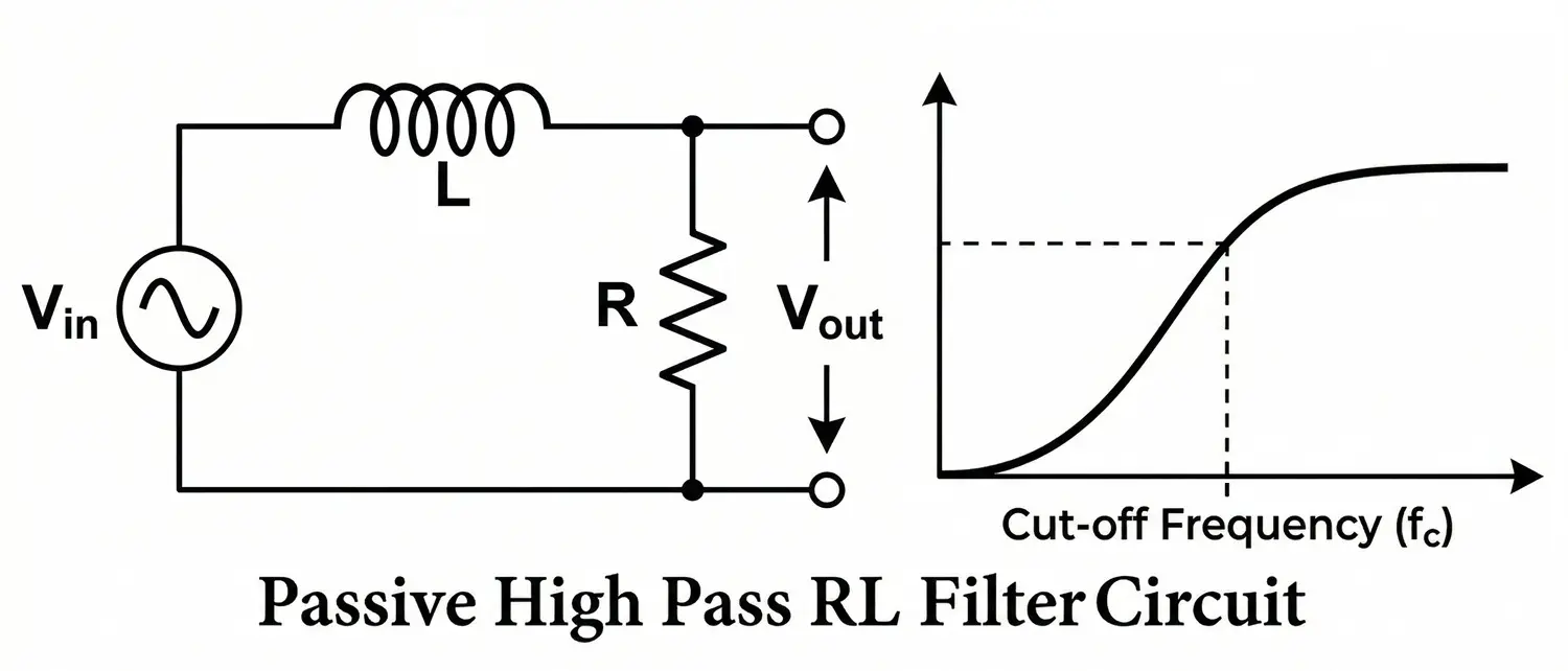
A high-pass RL filter consists of:
- Resistor in series with input
- Inductor connected to ground
- Output taken across the inductor
Working Principle:
- At low frequencies: XL is small → signal bypassed → output low
- At high frequencies: XL is large → voltage develops across inductor → output increases
Thus, high frequencies pass, low frequencies are attenuated.
Transfer Function:
H(s) = sL / (R + sL)
Phase Response:
- +90° at very low frequency
- +45° at cutoff
- 0° at high frequency
Frequency Response
Low-Pass RL Filter Waveform
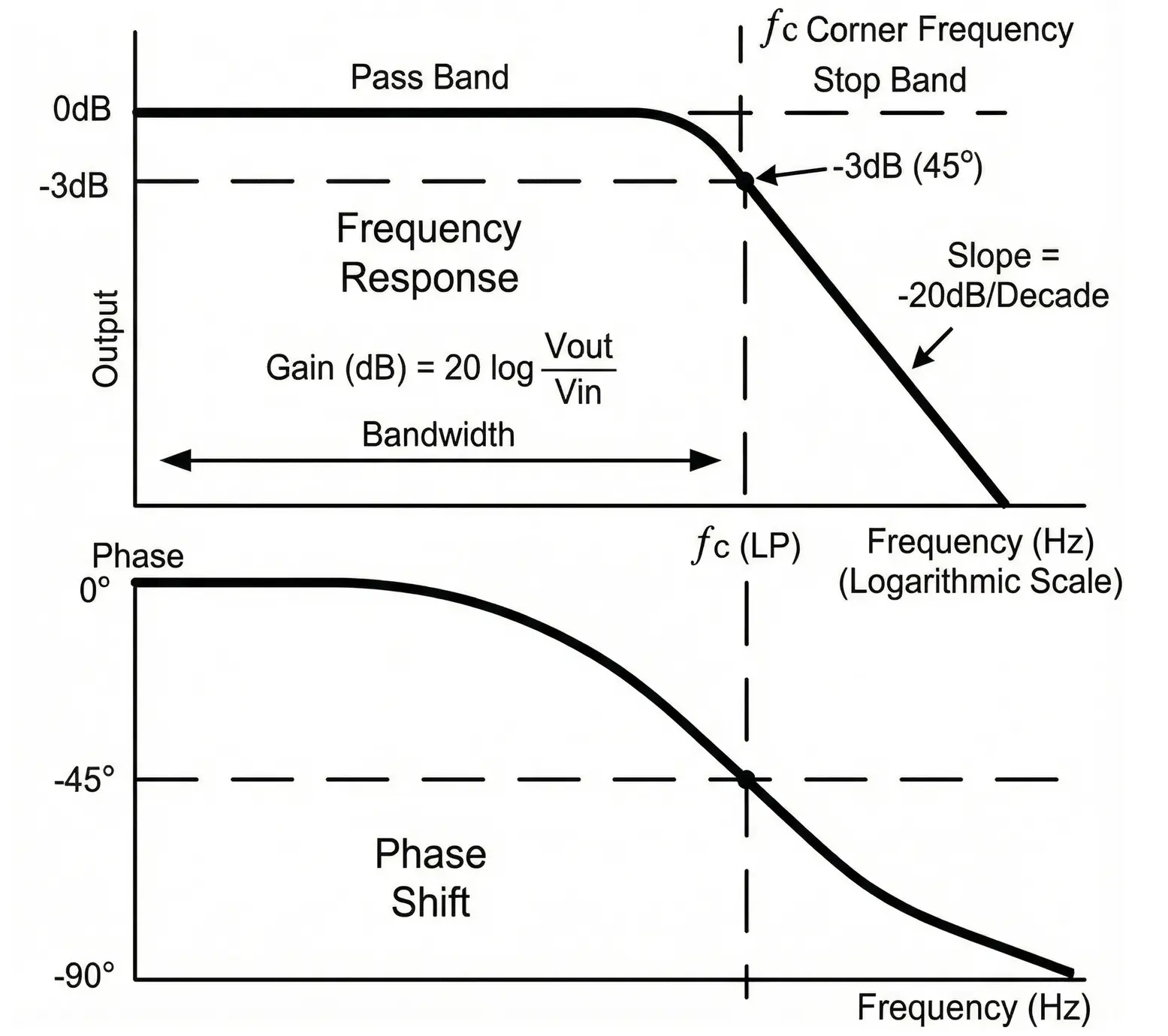
- Magnitude:
- Low frequency → Output ≈ Input
- At cutoff → −3 dB
- High frequency → −20 dB/decade
- Phase:
- Starts at 0°
- −45° at cutoff
- Approaches −90°
High-Pass RL Filter Waveform
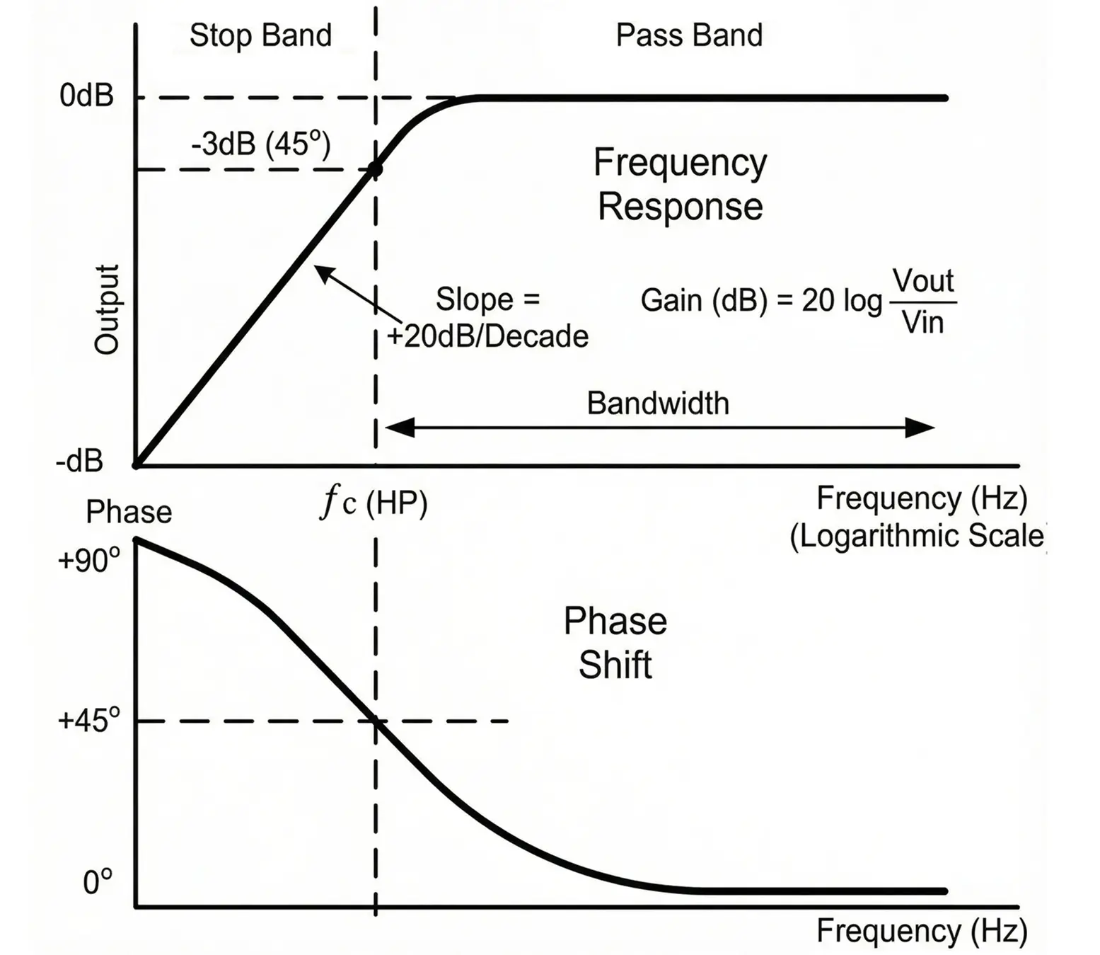
- Magnitude:
- Low frequency → Output ≈ 0
- At cutoff → −3 dB
- High frequency → Output ≈ Input
- Phase:
- +90° at low frequency
- +45° at cutoff
- Approaches 0°
Practical Considerations
- Inductor internal resistance affects performance
- Core saturation at high current
- Magnetic interference and EMI
- Large physical size compared to RC filters
- Parasitic capacitance limits high-frequency operation
- Loading effects shift cutoff frequency
Mathematical Analysis
Here is a mathematical analysis of RL low-pass and high-pass filters using voltage divider principle.
H(jω) = Zoutput / (R + jωL)
For a series RL circuit:
ZL = jωL
Total impedance:
Ztotal = R + jωL
RL Low-Pass Filter
Output Across Resistor R:
H(jω) = R / (R + jωL)
Magnitude:
|H(jω)| = R / √(R² + (ωL)²)
Phase:
φ = −tan−1(ωL / R)
Behavior:
- At low frequency (ω → 0): |H| ≈ 1 → Signal passes
- At high frequency (ω → ∞): |H| → 0 → Signal attenuated
RL High-Pass Filter
Output Across Inductor L:
H(jω) = jωL / (R + jωL)
Magnitude:
|H(jω)| = ωL / √(R² + (ωL)²)
Phase:
φ = tan−1(R / ωL)
Behavior:
- At low frequency (ω → 0): |H| → 0 → Signal blocked
- At high frequency (ω → ∞): |H| ≈ 1 → Signal passes
Cutoff Frequency
Cutoff occurs when inductive reactance equals resistance:
XL = R
Since XL = ωL:
ωcL = R
ωc = R / L
In terms of frequency:
fc = R / (2πL)
At Cutoff Frequency:
- Output voltage = 0.707 × Input
- Power reduced to 50%
- Phase shift = 45° (−45° for low-pass, +45° for high-pass)
Design Procedure
- Specify required cutoff frequency fc.
- Choose a practical inductor value L.
- Calculate resistor value:
R = 2πfcL
- Select nearest standard resistor value.
- Verify response using calculation or simulation.
Example Design
Given:
fc = 1 kHz
Choose:
L = 10 mH
Calculate:
R = 2π×1000×0.01
R ≈ 62.8 Ω
Select standard value:
R = 62 Ω
Advantages of RL Filters
- Simple design
- Suitable for higher power than RC filters
- Good current smoothing capability
- No capacitor aging issues
- Reliable for power electronics
Disadvantages of RL Filters
- Inductors are bulky and costly
- Magnetic coupling may cause interference
- Lower selectivity than LC filters
- Passive circuit (no gain)
- Energy loss in resistor
Applications of RL Filters
- Power supply ripple filtering
- Motor drive circuits
- Speaker crossover networks
- RF impedance matching
- Transient suppression
- PWM output smoothing in SMPS
Summary Table
| Parameter | RL Low-Pass | RL High-Pass |
|---|---|---|
| Output Taken Across | Resistor | Inductor |
| Passes | Low Frequency | High Frequency |
| Cutoff Frequency | R / 2πL | R / 2πL |
| Roll-Off | −20 dB/decade | −20 dB/decade |
| Phase Shift | 0° to −90° | +90° to 0° |
| Energy Storage Element | Inductor | Inductor |
Conclusion
RL filters are first-order passive filters that utilize the frequency-dependent behavior of inductive reactance to control signal bandwidth. They are particularly valuable in power electronics, current smoothing, and transient control applications, where inductors are naturally preferred over capacitors.
Although they are bulkier than RC filters and offer limited selectivity, RL filters remain essential wherever current control and magnetic energy storage are required.
Passive RC Filters: Circuit Diagram, Types, Working and Applications
Types of Filter Circuits: Working Principles, Formula & Applications
Different Types of Inductors Their Properties and Applications
