A zero crossing detector circuit is a simple electronic circuit used to detect the instant when the AC (alternating current) signal crosses the zero voltage point. It is commonly used in various applications such as in power control circuits, phase control circuits, motor control circuits, and in instrumentation.
Zero Crossing Detector Circuit
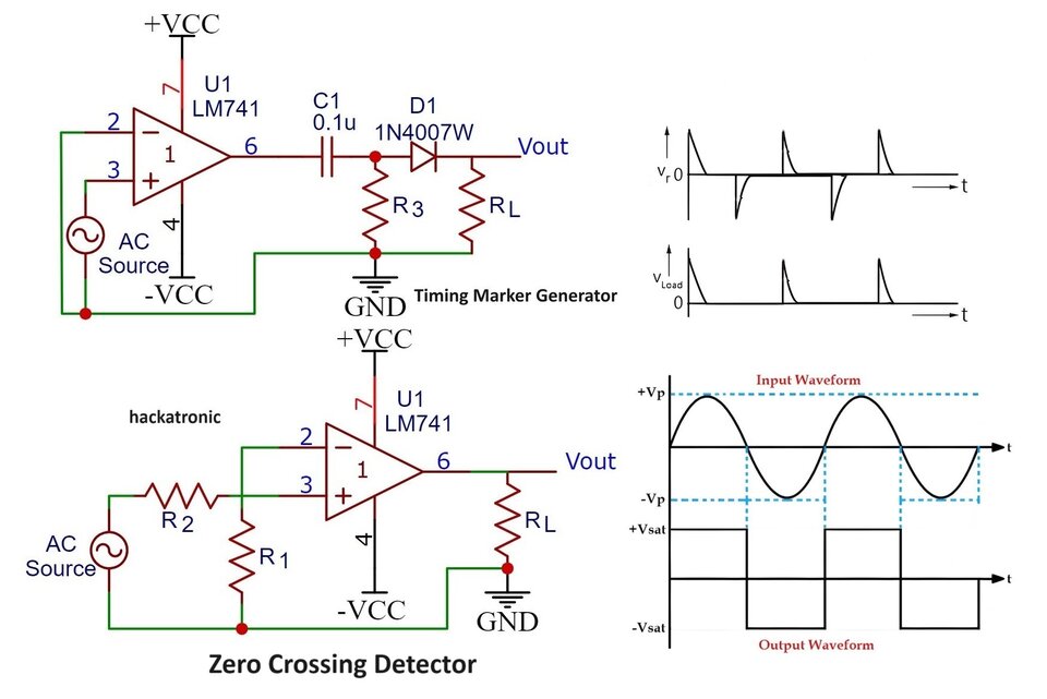
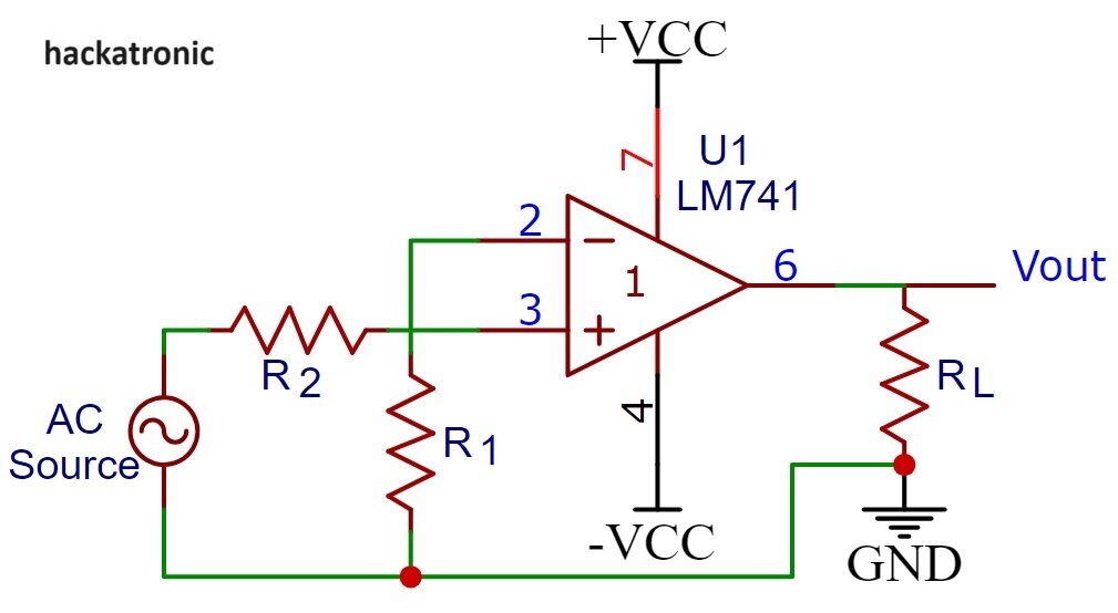
Here’s a basic schematic diagram of a zero crossing detector circuit using an Operational Amplifier (Op-Amp):
Components and Working of Zero Crossing Detector:
Operational Amplifier (Op-Amp): The Op-Amp is configured as a voltage comparator. When the input voltage (Vin) is positive, the Op-Amp output is high; when the input voltage is negative, the Op-Amp output is low.
Resistors (R1 and R2) are in series. R1 is connected between inverting input and ground. while R2 is connected between the input voltage (Vin) and the non-inverting input of the Op-Amp. RL is the load resistor.
Output: The output of the Op-Amp indicates the zero crossing of the input AC signal. When the input AC signal crosses zero volts, the voltage at the inverting input of the Op-Amp equals the threshold voltage set by the voltage divider. At this point, the Op-Amp changes its output state, indicating the zero crossing event.
Operation of Circuit:
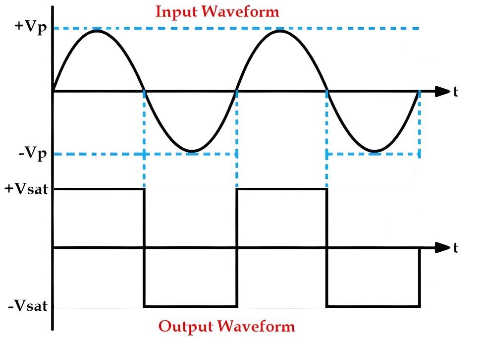
When the input AC signal is positive, the voltage at the inverting input of the Op-Amp is higher than the voltage at the non-inverting input, causing the Op-Amp output to be high.
When the input AC signal crosses zero volts and becomes negative, the voltage at the inverting input drops below the threshold voltage, causing the Op-Amp output to switch to low.
This change in the Op-Amp output state indicates the zero-crossing event of the input AC signal.
Zero crossing detectors are essential in many applications where precise timing or synchronization is required, such as in phase-locked loops, power factor correction circuits, and digital phase control circuits.
By design there are two types of zero crossing detectors
Inverting zero crossing detector
Output waveform is inverted with respect to input signal.
Non-inverting zero crossing detector
Output waveform is in same alignment with respect to input signal.
Time Marker Generator Circuit
A Time Marker Generator utilizing a zero-crossing detector can be a useful circuit in applications where precise timing is required, such as in power systems for synchronization purposes or in music synthesizers for generating control signals. Below is a conceptual description of how such a circuit could be designed.
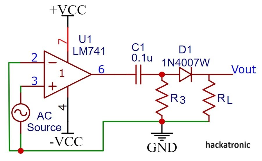
A simple zero crossing detector has been used for making square wave pulses. These waves are passed through a RC circuit which outputs a continuous spiky wave after fixed timing. These waves are passed through diode to get marker waveform.
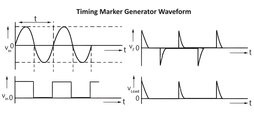
You can see the time marker generator waveform in the above image.
If the time constant RC is much smaller than the period T of the input sine wave, the voltage across R (Vr) in the RC circuit produces alternating positive and negative pulses. When Vr is applied to a clipper circuit with a diode D, the resulting load voltage Vload only contains positive pulses, removing the negative ones. Hence, by adding an RC network and a clipping circuit, a zero-crossing detector turns a sine wave input into a series of positive pulses spaced apart by T intervals.
Applications of Zero Crossings Detector:
Zero crossing detector circuits are commonly used in various electronic applications for detecting the points in time when the AC voltage waveform crosses zero volts. Here are some key applications of zero crossing detector circuits:
Switching Power Supplies:
Zero crossing detectors are used in switching power supplies to synchronize the switching of power transistors with the AC voltage waveform. This synchronization helps minimize electromagnetic interference (EMI) and reduces power loss.
Dimmer Control:
In lighting control systems, zero crossing detectors are utilized to synchronize the switching of dimming circuits with the AC voltage waveform. This ensures smooth and flicker-free dimming of lights, especially for dimmable LED lamps.
Motor Control:
Zero crossing detectors are employed in motor control circuits to synchronize the switching of semiconductor devices (such as thyristors or triacs) with the AC waveform. This allows for precise control of motor speed and direction.
Audio Signal Processing:
Zero crossing detectors are used in audio signal processing applications for detecting the zero-crossing points of audio waveforms. This information is useful for tasks such as audio phase detection, zero-phase distortion filtering, and frequency measurement.
Temperature Sensing:
Zero crossing detectors can be utilized in temperature sensing circuits for measuring the resistance of temperature-sensitive devices (such as thermistors or RTDs) based on their response to AC excitation. This technique helps eliminate thermal offset errors.
Time Measurement:
Zero crossing detectors can be employed in time measurement applications where precise timing is required. By measuring the time intervals between successive zero crossings, accurate time measurements can be achieved.
AC Voltage Regulation:
In AC voltage regulation circuits, zero crossing detectors are used to detect the phase of the AC voltage waveform relative to a reference signal. This information is utilized to control the switching of voltage regulators for maintaining stable output voltage levels.
Signal Synchronization:
Zero crossing detectors are used in communication systems and data transmission applications for synchronizing the timing of transmitted signals with the AC mains frequency. This helps prevent signal distortion and timing errors.
These are just a few examples of the numerous applications of zero crossing detector circuits. Their ability to accurately detect the zero-crossing points of AC waveforms makes them invaluable in a wide range of electronic systems and devices.
