In this tutorial, you will learn how to make this over-voltage protection circuit. It requires fewer components and is very effective in overvoltage conditions. It will cost you around 3$ to 5$ depending on the quality of components.
Overvoltage occurs when the voltage in a circuit is raised above its upper design limits. This condition may be hazardous depending upon its duration. It can be transient, voltage spike, or permanent causing power surge.
Overvoltage and continuous voltage fluctuations are the major problems of domestic power supplies in many areas. It can cause permanent damage to electrical and electronic home appliances. Some of our home appliances come with protection circuits but not all of them have protection against overvoltage.
Components Required for this Circuit:
Along with these components, you need an AC voltage regulator (a fan speed controller is useful) and a multimeter for measurements and corrections.
- One Green and one Red LED.
- 47kΩ resistor X2 pieces.
- BC547 transistor.
- 10uF/25V electrolytic capacitor.
- 100uF/25V electrolytic capacitor.
- 12V relay module.
- 10kΩ potentiometer.
- 2 pin screw terminal X3 pieces.
- 1N4007 PN junction diode X2 pieces.
- 1kΩ resistor X2 pieces.
- 1 piece zero PCB board.
Circuit Connection Explanation:
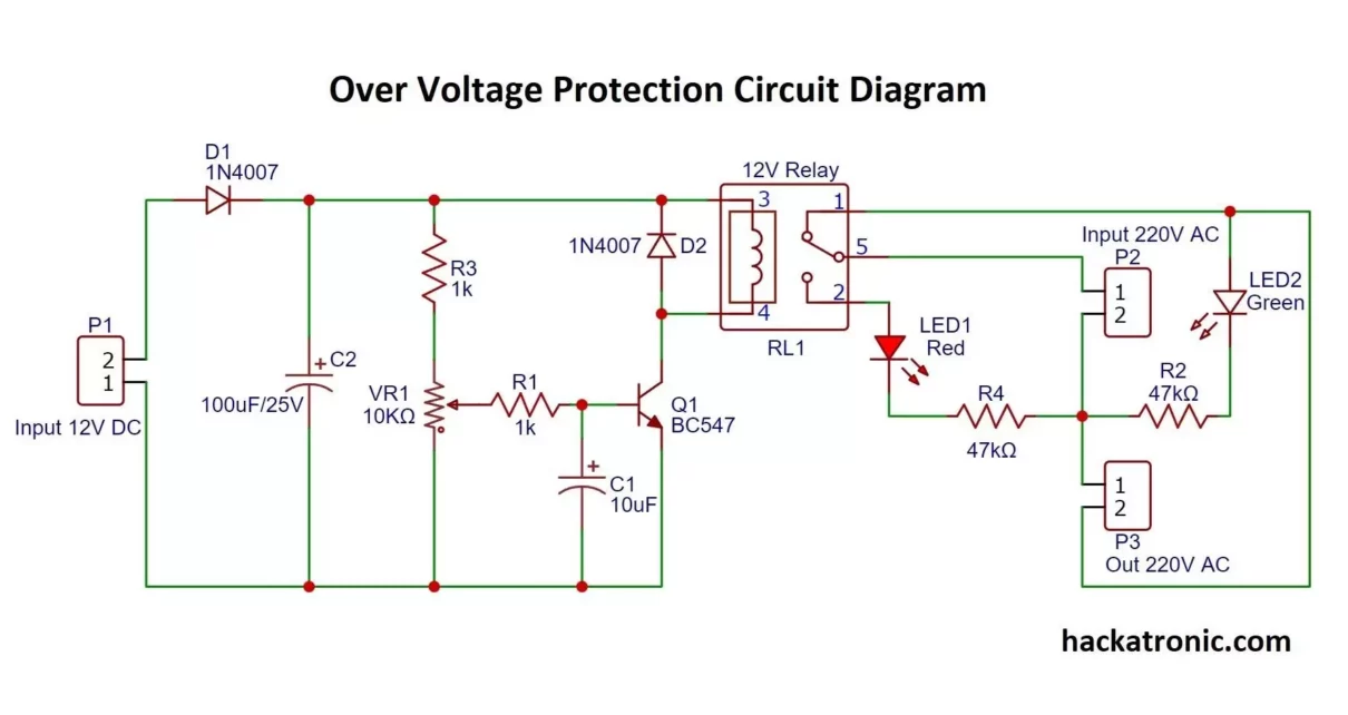
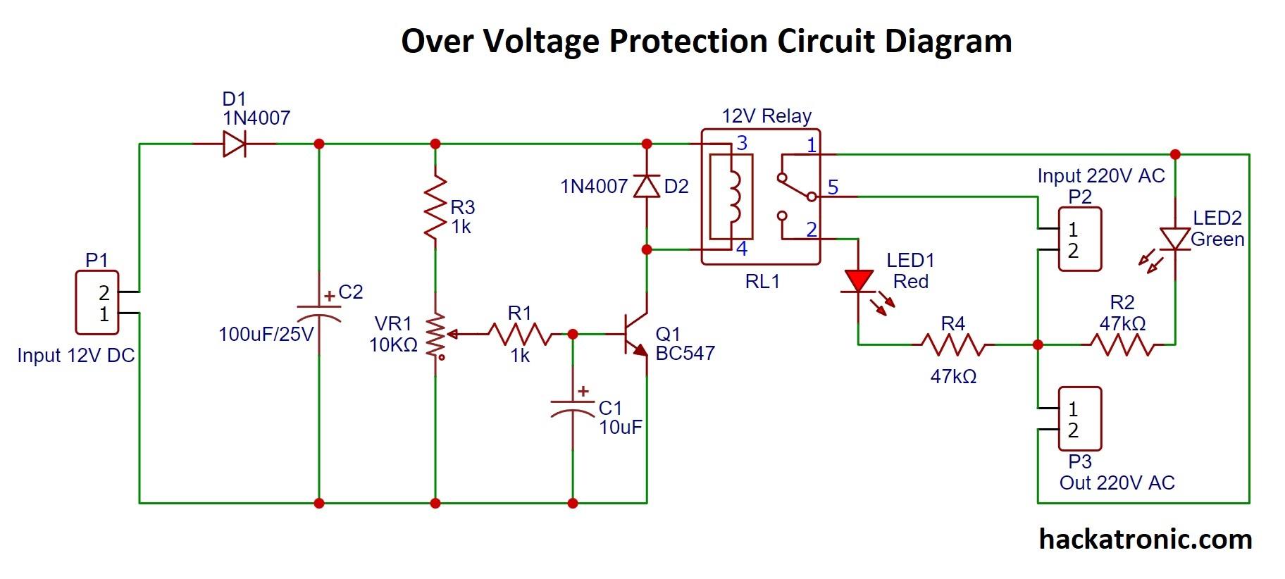
In this circuit, you can see that there are two different powers DC and AC. Relay is used to control the AC load section and we are controlling relay via DC circuit. You can get 12V DC by a transformer after rectification and filtering or you can use any different power source.
In the above circuit 12V, DC is given at Port P1, diode D1, and capacitor C2 are used to filter the DC power. Diode D2 is connected in parallel to protect the relay. Transistor BC547 drives the relay it is connected between the ground and second pin of the relay. 10kΩ potentiometer controls the base terminal of the transistor, we can adjust the cut-off voltage by rotating the knob of the potentiometer. Capacitor C1 again acts as a noise filter.
On the other side of the relay, there are 220V input and output ports. The relay is a single pole double throw type relay. The normally open terminal is connected to the Red LED which is connected to neutral via 47kΩ resistance. Whereas the normally closed terminal connects to the output port. The Green LED shows the ON state of the output port P3.
Working of Relay based over-voltage protection circuit:
To understand the working of this circuit consider that we want to cut off the circuit at 220V. Now using the fan’s voltage regulator adjust the voltage of the input to AC 220V also connect a load like a bulb. Then rotate the knob of the potentiometer very slowly till you hear a loud click sound from relay and the bulb turns off. Now, this circuit is set to cut off at 220 volt AC. To turn on the circuit start reducing input voltage from the fan regulator. At around 210V AC you will hear a click sound and the light will again turn on. This effect is due to hysteresis in the relay circuit, you should adjust your cut-off voltage considering this hysteresis.
When power is applied to the circuit the maximum voltage drops across resistor R1, R3, and variable resistor VR1 keeping the transistor off. As soon as the input AC voltage reaches the cut-off voltage, the voltage appearing at the base of the transistor via potentiometer also increases and it turns the transistor to ON state and this transistor drives the relay to cut off the output circuit from the input.
Watch this video for a better understanding:
If you have any queries comment Down.

There is no feedback from the AC side to the DC side
The AC can be any voltage and there will be no change to the relay
The only way this would work is if you used a transformer powered from the mains for your ‘12V’ supply and you did not regulate its output.
we are getting 12V from a transformer connected to the same circuit
yes