A Voltage Controlled Oscillator (VCO) using 555 timer is an oscillator whose output frequency is directly dependent on the input control voltage. VCOs are widely used in communication systems, tone generators, frequency modulation (FM), and various signal processing applications.
One of the simplest and most economical ways to build a VCO is by using the versatile 555 Timer IC in astable mode. In this article, we’ll explore how to build a 555 timer-based VCO, how it works, and its practical applications.
Components Required
- NE555 Timer IC
- Capacitor (C): 0.01 µF to 1 µF
- Resistors: R1, R2 (potentiometer or fixed), e.g., 2kΩ and 10kΩ
- Control Voltage Source (0V to ~9V)
- Power Supply (5V to 15V)
- Breadboard or PCB for prototyping
- Connecting wires
- Oscilloscope (optional, for observing waveform)
555 Timer Pinout
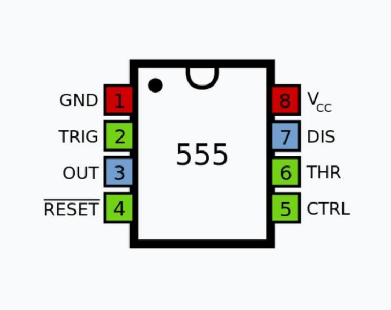
- Pin 1 – GND: Connects to ground (0V).
- Pin 2 – Trigger: Starts timing when voltage drops below 1/3 Vcc.
- Pin 3 – Output: Provides high or low output signal.
- Pin 4 – Reset: Resets the timer when low; tie to Vcc if unused.
- Pin 5 – Control Voltage: Modifies internal threshold; connect capacitor to ground if unused.
- Pin 6 – Threshold: Ends timing when voltage exceeds 2/3 Vcc.
- Pin 7 – Discharge: Discharges capacitor; connects to timing resistor.
- Pin 8 – Vcc: Positive power supply (5V–15V).
Construction of VCO Using 555 Timer
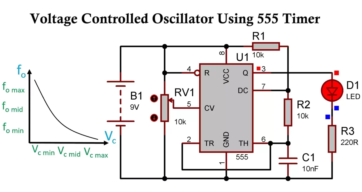
The 555 timer is configured in astable mode, where the frequency of oscillation is determined by the values of two resistors and a capacitor. In a VCO configuration, we take advantage of Pin 5 (Control Voltage) to modulate the internal threshold and trigger levels of the timer, thereby affecting the output frequency.
Circuit Diagram
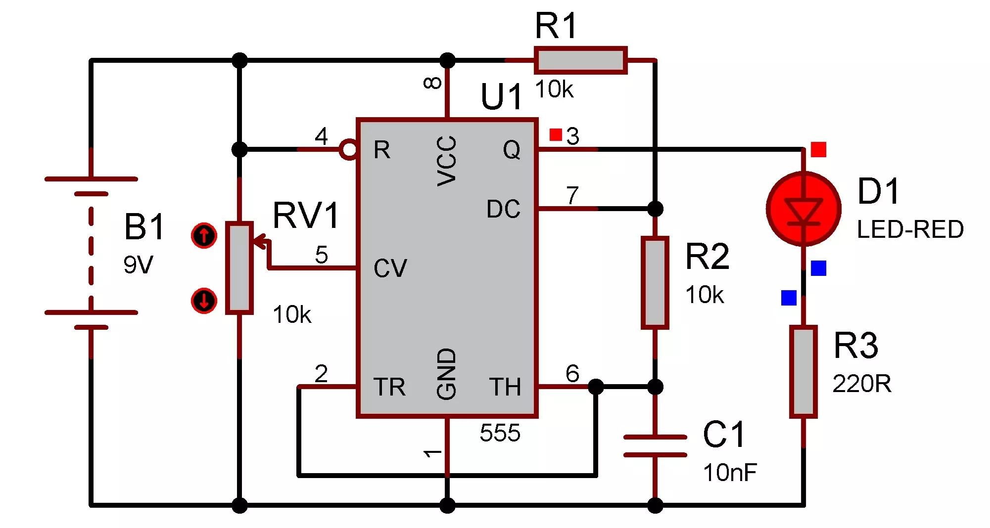
- Connect Vcc (Pin 8) to the positive rail and GND (Pin 1) to the negative rail.
- Connect Pin 4 (RESET) to Vcc to enable the IC.
- Connect a timing capacitor (C) between Pin 6 (Threshold) and GND.
- Short Pin 2 (Trigger) and Pin 6 together.
- Connect R1 between Vcc and Pin 7 (Discharge).
- Connect R2 between Pin 7 and Pin 6/2.
- Apply a variable control voltage (0V–9V) to Pin 5 using a potentiometer or external analog source.
- The output waveform is available at Pin 3.
- Connect an LED to see the output or use an oscilloscope to see the waveform.
Working of Voltage Controlled Oscillator Using 555 Timer
In astable mode, the 555 timer produces a continuous square wave. The timing capacitor charges and discharges between 1/3 Vcc and 2/3 Vcc thresholds set internally. By default, these levels are fixed, but when a voltage is applied to Pin 5 (Control Voltage), it overrides the internal 2/3 Vcc reference.
This means:
- Increasing the control voltage raises the upper threshold level.
- This causes the capacitor to take longer to reach the higher level, thus reducing the frequency.
- Decreasing the control voltage lowers the threshold, speeding up charge cycles, thereby increasing the frequency.
Frequency Formula:
The approximate frequency of oscillation is given by:
f = 1.44/(R1+2R2)⋅C
However, in the VCO setup, the capacitor charge and discharge times vary with the control voltage (Vcontrol) on Pin 5, so this formula becomes dependent on Vcontrol indirectly.
Here is a Tinkercad simulation of voltage-controlled oscillator VCO using 555 timer IC.
Advantages of 555 Timer VCO
- Simple and Inexpensive – Minimal components required.
- Easy to Construct – Beginner-friendly project for learning VCO basics.
- Flexible Frequency Range – Adjustable with R1, R2, and C.
- Stable Output – Produces reliable square wave for many applications.
- Compact Design – Easily fits in small circuits and modules.
Disadvantages of 555 Timer VCO
- Limited Linearity – The frequency change is not perfectly linear with voltage.
- Limited Accuracy – Component tolerances affect frequency stability.
- Narrow Tuning Range – Difficult to get very wide frequency sweeps without special designs.
- Noise Sensitivity – Pin 5 is prone to noise which can affect stability.
- Square Wave Output Only – Additional circuitry is required to generate sine or triangle waves.
Applications of 555 Timer-Based VCO
- Tone Generators – For audio frequency testing and simple sound devices.
- Function Generators – Produces basic square waves for testing circuits.
- Frequency Modulation (FM) – In radio transmission or data modulation systems.
- Signal Sweeping Circuits – For checking frequency response of filters and amplifiers.
- Light/Sound Controlled Oscillators – Using sensors to modulate frequency.
- Pulse Width Modulators – As part of analog control circuits.
- Voltage to Frequency Converters – In analog-to-digital interface applications.
Tips for Better Performance
- Bypass Pin 5 with a 0.01µF capacitor to ground to reduce noise.
- Use precision resistors and capacitors for more accurate frequency control.
- You can add an op-amp buffer on the control voltage line for stability.
- Use a potentiometer in place of R2 to manually control the frequency.
Conclusion
A Voltage Controlled Oscillator (VCO) using a 555 timer IC is a great example of analog signal control. It’s perfect for hobbyists and students who want to understand frequency modulation and oscillator design. Though it has its limitations, the simplicity and flexibility make it an excellent tool for experimentation and learning.
Different Types of Oscillators with Working and Applications
Astable Multivibrator Circuit Diagram, Working and Applications
