Explore the LLC Resonant Converter SMPS Circuit Diagram covering both Half-Bridge and Full-Bridge topologies with construction, working, (source, MOSFETs, PWM drive, inductors, capacitors), protections, advantages, disadvantages, and practical applications.
LLC Resonant Converter SMPS Circuit Diagram
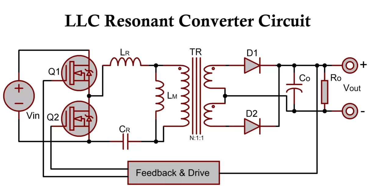
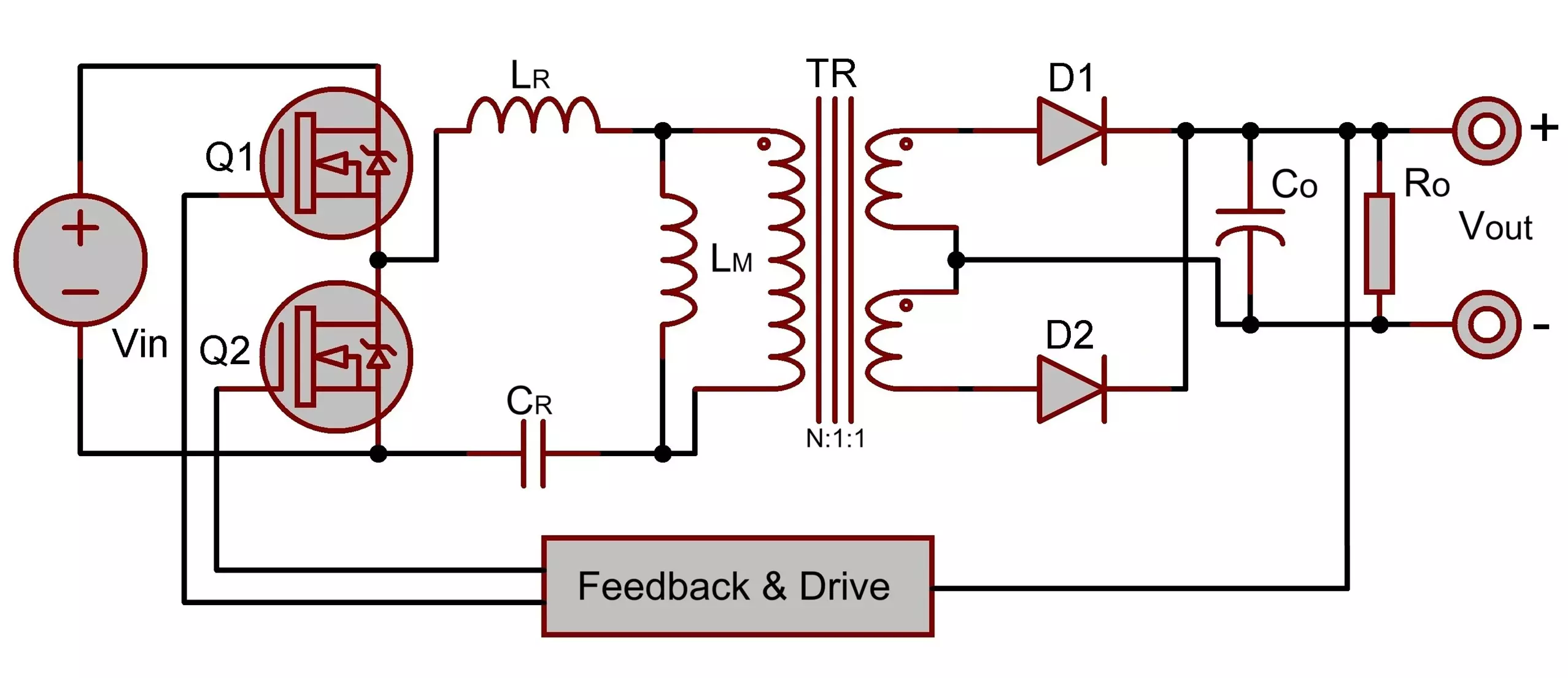
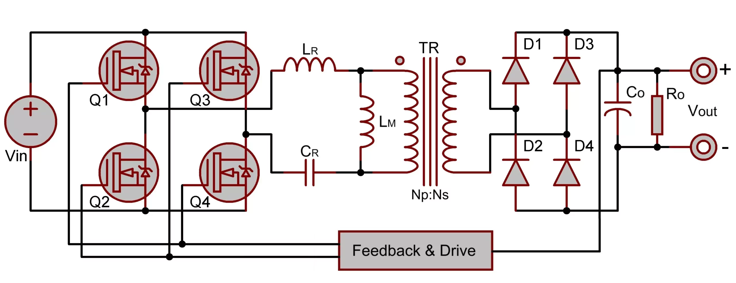
The LLC resonant converter is a high-efficiency topology widely used in Switched Mode Power Supplies (SMPS), particularly in applications requiring isolation, soft switching, and high-power density. The “LLC” name derives from the series resonant inductor (Lr), magnetizing inductance (Lm) of the transformer, and a resonant capacitor (Cr).
There are two primary configurations:
- Half-Bridge LLC Resonant Converter
- Full-Bridge LLC Resonant Converter
Both are based on zero-voltage switching (ZVS) to minimize switching losses and electromagnetic interference (EMI).
Common Elements in Both Topologies:
- AC Input Source
- EMI Filter
- Bridge Rectifier
- DC Link Capacitor
- MOSFET Switching Network (Half or Full Bridge)
- LLC Resonant Tank (Lr, Lm, Cr)
- High-Frequency Transformer
- Secondary Rectifier
- Output Filter
- PWM Controller with Frequency Modulation
- Protection Circuits (OCP, OVP, UVP, OTP)
Half-Bridge LLC Resonant Converter Circuit Diagram
Full-Bridge LLC Resonant Converter Circuit Diagram
Construction of LLC Resonant Converter
a. AC Source and Input Filter
- EMI Filter: Suppresses conducted noise.
- Bridge Rectifier: Converts AC to DC.
- DC Link Capacitor: Filters ripple and stabilizes the DC bus.
b. Switching Stage
- Half-Bridge: Uses 2 MOSFETs.
- Full-Bridge: Uses 4 MOSFETs for higher power output.
- Gate Driver IC: Provides isolated PWM drive, e.g., IR2110, UCC25600, or dedicated LLC controllers like L6599.
c. Resonant Tank
- Lr: Series inductor for resonance.
- Cr: Resonant capacitor to form LC circuit.
- Lm: Magnetizing inductance of the transformer — provides zero-current switching (ZCS) at output rectifiers and helps shape gain curve.
d. Transformer
- High-frequency ferrite core (e.g., EE, ETD types).
- Provides galvanic isolation and voltage step-up/down.
how Lr and Lm are implemented in the transformer’s primary side in an LLC resonant converter.
1. Lm (Magnetizing Inductance) — Core-Linked Flux
Physically implemented by:
- Number of primary turns (N₁) wound on the core.
- Core material (like ferrite) — determines permeability (μ).
- Core geometry — affects magnetic path length and cross-sectional area.
- Tight magnetic coupling between windings (maximized mutual flux).
Where it comes from:
- All the magnetic flux that links both primary and secondary windings is responsible for Lm.
- This is the “main” inductance of the transformer — calculated using:
Lm = N1^2⋅μ⋅A/l
where:
- N1 = number of primary turns
- μ = permeability of the core
- A = cross-sectional area of the core
- l = magnetic path length
2. Lr (Resonant or Leakage Inductance) — Non-Linked Flux
Physically implemented by:
- Winding layout — how primary and secondary are arranged relative to each other.
- Physical distance between primary and secondary windings.
- Avoiding interleaving of windings (interleaving reduces leakage — which is bad if you want high Lr).
Where it comes from:
- Flux that stays only in the primary winding and doesn’t link to the secondary.
- This flux “leaks” around the core or takes a separate path, and its energy is stored outside the main mutual flux path — this is your Lr.
Visual Analogy:
Imagine a transformer core with two coils:
- The tight, centrally located magnetic flux linking both coils gives you Lm.
- The stray, fringe field from the primary that doesn’t couple to the secondary gives you Lr.
Summary:
| Parameter | Source | Physically Controlled By |
|---|---|---|
| Lm(magnetizing) | Linked flux | Core material, core shape, number of primary turns |
| Lr(leakage/resonant) | Unlinked flux | Winding layout, separation between primary and secondary, placement of windings |
e. Rectification & Output Filter
- Synchronous Rectifiers (MOSFETs) or Schottky Diodes for fast recovery.
- LC Filter on the secondary side ensures low ripple DC output.
f. Protection Circuits
Protection circuits are built-in safety mechanisms in electronic devices and power supplies to prevent damage from abnormal electrical conditions. Here’s what each type does:
1. Over-Current Protection (OCP)
Purpose: Protects circuits from drawing too much current.
How it works:
If the current exceeds a safe threshold, the circuit will shut down, limit the current, or blow a fuse.
Why it matters: Prevents overheating, fire hazards, and damage to components.
2. Over-Voltage Protection (OVP)
Purpose: Prevents the voltage from going higher than the device can handle.
How it works:
The circuit detects high voltage and either diverts or shuts off power to protect downstream components.
Why it matters: Excess voltage can destroy semiconductors and capacitors.
3. Under-Voltage Protection (UVP)
Purpose: Protects devices from operating when voltage drops too low.
How it works:
When voltage falls below a safe level, the circuit may shut off the device or signal a warning.
Why it matters: Low voltage can cause malfunction, data loss, or erratic behavior.
4. Over-Temperature Protection (OTP)
Purpose: Prevents overheating of components.
How it works:
Temperature sensors detect overheating, triggering shutdown or reducing power.
Why it matters: Overheating can permanently damage internal electronics and reduce lifespan.
Working of LLC Resonant Converter Circuit
a. Resonant Operation
- Converter operates by varying switching frequency to track the resonant frequency of the Lr-Cr circuit.
- Below resonance: Lagging power factor, ZVS is achievable.
- At resonance: High efficiency, maximum gain.
- Above resonance: Leading power factor, reduced gain but safer operation.
b. Frequency Control
- No duty-cycle modulation; instead, frequency modulation controls the output voltage.
- Lower frequency increases gain, higher frequency reduces gain.
c. Soft Switching (ZVS)
- The switching occurs when voltage across MOSFETs is nearly zero, minimizing losses and EMI.
- Achieved using resonant behavior of Lr and Cr.
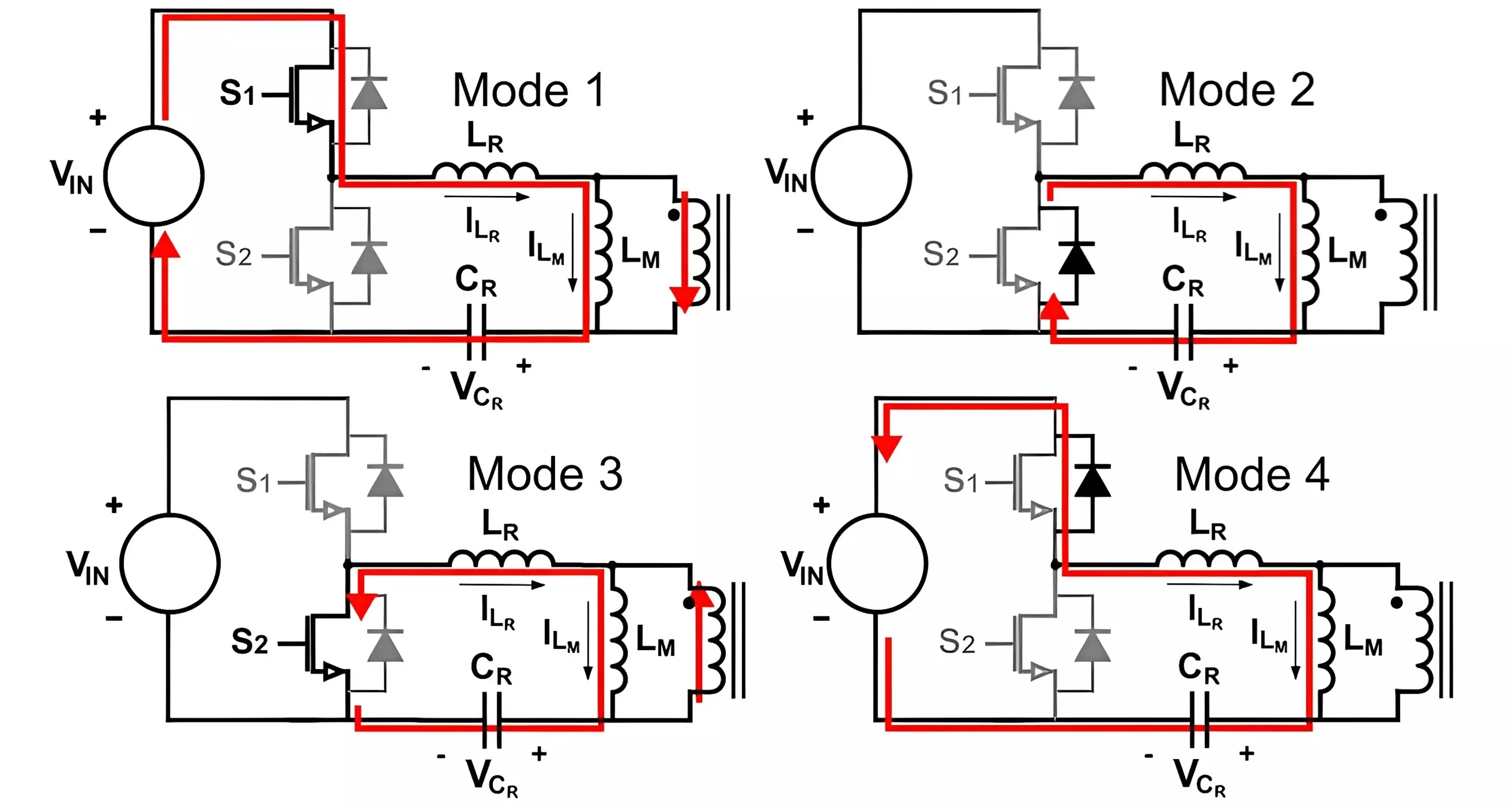
d. Energy Transfer
- Alternating operation of bridge switches creates an alternating voltage across the resonant tank.
- The tank filters and shapes the waveform fed into the transformer.
- Transformer steps the voltage and provides isolation.
- Secondary rectifiers convert AC to DC, filtered before delivery.
Differences Between Half-Bridge and Full-Bridge LLC Converter
| Feature | Half-Bridge | Full-Bridge |
|---|---|---|
| Power Handling | Medium power (100W–500W) | High power (>500W–kW range) |
| MOSFETs Required | 2 | 4 |
| Complexity | Simpler | More complex |
| Cost | Lower | Higher |
| Transformer Utilization | 50% | 100% |
| Efficiency Potential | Slightly lower | Higher due to full waveform usage |
Advantages of LLC Resonant Converters
- High efficiency (up to 96%)
- Soft switching: ZVS for primary MOSFETs and ZCS for secondary diodes
- Low EMI due to smooth waveforms
- Compact size and light weight
- Transformer isolation
- Better thermal management due to reduced switching loss
Disadvantages of LLC Resonant Converters
- Design is more complex than traditional PWM SMPS
- Resonant components require precise values
- Feedback control loop is more difficult to stabilize
- Poor load regulation if improperly designed
Applications of LLC Resonant Converters
- Server and Telecom Power Supplies
- High-performance ATX/ITX Power Supplies
- Onboard Chargers in Electric Vehicles (EV)
- Industrial Automation Equipment
- RF and Broadcast Transmitters
- High-efficiency Battery Chargers
- Medical and Imaging Equipment
Popular LLC Resonant Controller ICs
| Part Number | Manufacturer | Key Features | Package |
|---|---|---|---|
| ICE2HS01G | Infineon | Half-bridge LLC, programmable oscillator, protections | SOIC-8 |
| ICE1HS01G-1 | Infineon | Updated version of ICE1HS01G, high-performance, soft-start | SOIC-8 |
| ICE2HS01GXUMA1 | Infineon | Extended version with more robust protection | SOIC-8 |
| L6599 / L6599A / D | STMicroelectronics | Advanced features, multiple protections, adjustable dead-time | SOIC-16/20 |
| FAN7621 / FAN7621S | onsemi (Fairchild) | HV startup, frequency modulation, efficiency enhancements | SOIC-16 |
| UCC25600 | Texas Instruments | Basic LLC controller, adaptive dead-time control | SOIC-16 |
| UCC256301 / 302 / 303 | Texas Instruments | Advanced LLC with hybrid control and built-in protections | SOIC-16 |
| TEA1716 | NXP | Combo IC (PFC + LLC), ideal for integrated power stages | SO16 |
| IRS27952 | Infineon (ex-IR) | Integrated HV start-up, excellent for resonant converters | SOIC-8 |
| HiperLCS-2 | Power Integrations | Integrated controller + gate drivers for compact LLC design | eSOP |
| HR1000A | MPS (Monolithic Power) | Low-power LLC controller, good for compact designs | QFN |
| FSFR2100 / 2100C | onsemi | Green mode LLC controller with HV startup | DIP-12, SOIC-16 |
Conclusion
The LLC Resonant Converter in both Half-Bridge and Full-Bridge forms is a cutting-edge SMPS design that offers high efficiency, low EMI, and excellent thermal performance. While it requires more intricate design skills and component matching, it is the preferred solution for modern power electronics demanding compactness, isolation, and high-power density.
Please check these two resources for detailed operation and design of resonant LLC converter. Resonant Mode Controller – Full Bridge, LLC resonant half-bridge converter
Linear Regulated Power Supply Block Diagram & Circuit Diagram
12V 10A SMPS: Switched Mode Power Supply Circuit – IC DM0565

Hello…
is this a copy of your design?
thank you
YouTube: hello tech market
https://www.youtube.com/watch?v=8qKbHeiuiPg
Yes
Hi, Do you have any half bridge LLC resonant converter circuit using ICE2HS01G.
No
Thank you for reply. Do you have half bridge LLC resonant circuit using above mentioned any IC.
You mentioned ICE2HS01G, I don’t have any circuit for this IC.