A Schmitt Trigger circuit is a comparator circuit with some modifications. As compared to a normal comparator circuit the Schmitt trigger circuit has a hysteresis curve. This means that it has two threshold voltages an upper threshold and a lower threshold voltage.

In Schmitt trigger hysteresis is created by applying positive feedback to the non-inverting input terminal of opamp comparator or differential amplifier.
This circuit is used as an analog to digital converter. In the Schmitt trigger circuit when the input voltage is higher than the upper threshold output of the circuit is high. The output of the circuit remains high even if the input goes below the threshold voltage. When the input signal becomes lower than the lower threshold voltage of Schmitt trigger comparator circuit output goes to a low state. In order to make the output high input voltage must be higher than the upper threshold voltage. Thus, the Schmitt trigger has two threshold voltages. This dual-threshold action is known as hysteresis.
The Schmitt trigger acts as a memory element or a latch. A Schmitt trigger can be converted into a latch and a latch can be converted into a Schmitt trigger.
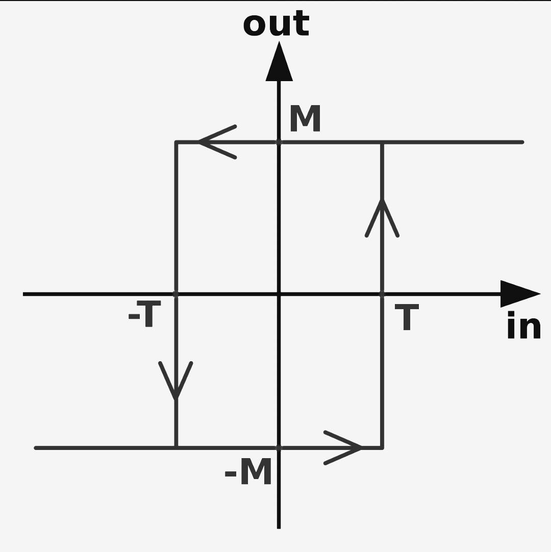
Transfer Characteristics of Schmitt Trigger Circuit:
From the transfer characteristics you can see that there are two thresholds of Schmitt trigger.
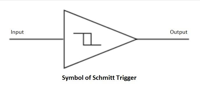
Types of Schmitt Trigger:
There are two types of Schmitt trigger inverting Schmitt trigger and non-inverting Schmitt trigger. here we will see Schmitt trigger using OPAMP. In opamp Schmitt trigger circuits there is positive feedback between output and the non-inverting input terminal of the opamp.
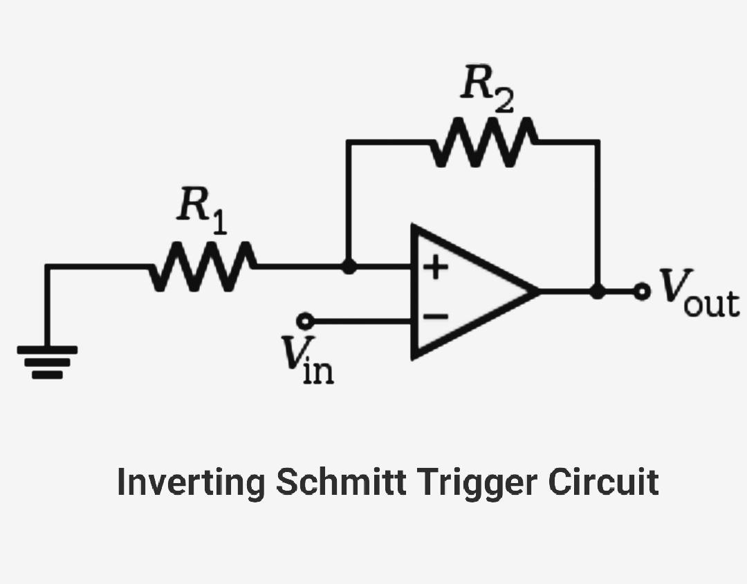
Inverting Schmitt trigger:
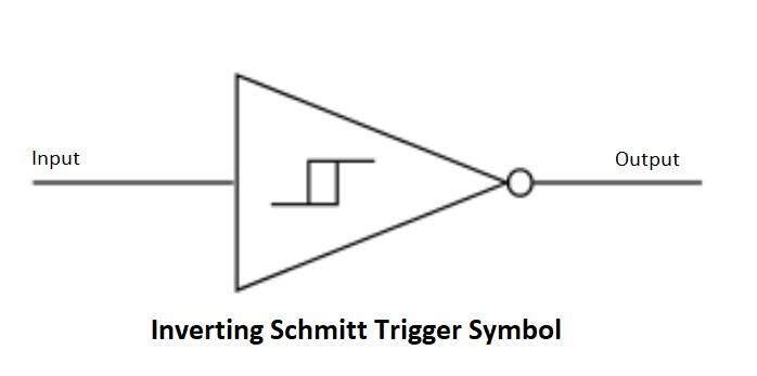
In inverting Schmitt trigger the input signal is applied to the inverting input terminal of the opamp. The output of the inverting Schmitt trigger is 180 degrees out of phase with respect to the input signal.
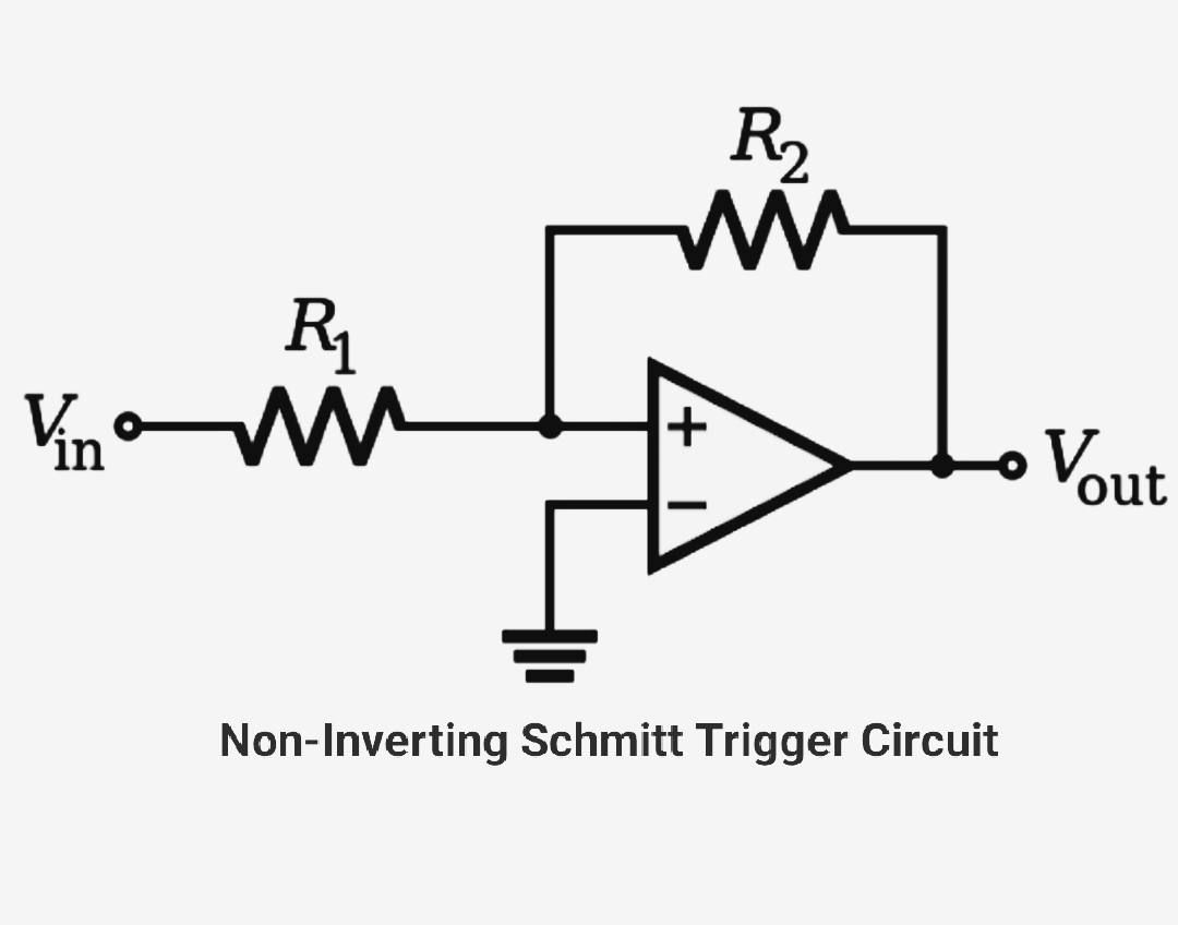
Non-inverting Schmitt trigger:
In non-inverting Schmitt trigger circuit input signal is applied to the non-inverting input terminal of the OPAMP. Here the output of the Schmitt trigger is in phase with the input signal.
Applications of Schmitt trigger:
Schmitt trigger is mainly used in signal processing to remove noise from signals used in digital circuits.
- They are used in closed-loop negative feedback configurations in relaxation oscillators.
- used in function generators.
- switching power supplies SMPS.