A Motion Sensor Light is an automatic lighting system that turns ON when it detects movement in its range and switches OFF after a certain period of inactivity. This system is widely used for energy conservation, security, and convenience.
The circuit described here uses a PIR (Passive Infrared) sensor, a BC547 transistor, a relay, and a 220V AC bulb. It can automatically control any electrical load (like a bulb or lamp) depending on human movement detected by the PIR sensor.
Main Components Required
- PIR Sensor Module (HC-SR501 or Equivalent)
- Detects motion by sensing infrared radiation changes from human bodies.
- Operates typically at 5V and gives a high output (3.3V) when motion is detected.
- Transistor – BC547
- Acts as a switch to drive the relay coil since the PIR sensor cannot directly power the relay.
- Relay (5V SPDT)
- Works as an electromagnetic switch to control the 220V AC bulb with the low-power control signal.
- Diode – 1N4007
- Connected in parallel with the relay coil (in reverse bias) to protect the transistor from back EMF generated during switching.
- Resistor – 220Ω
- Used as a base resistor for the BC547 transistor to limit the base current.
- AC Bulb (220V)
- The output load which turns ON automatically when motion is detected.
- Power Supply
- 5V DC for the relay and transistor circuit. 5V DC can be derived using a 7805-voltage regulator if you have a higher voltage.
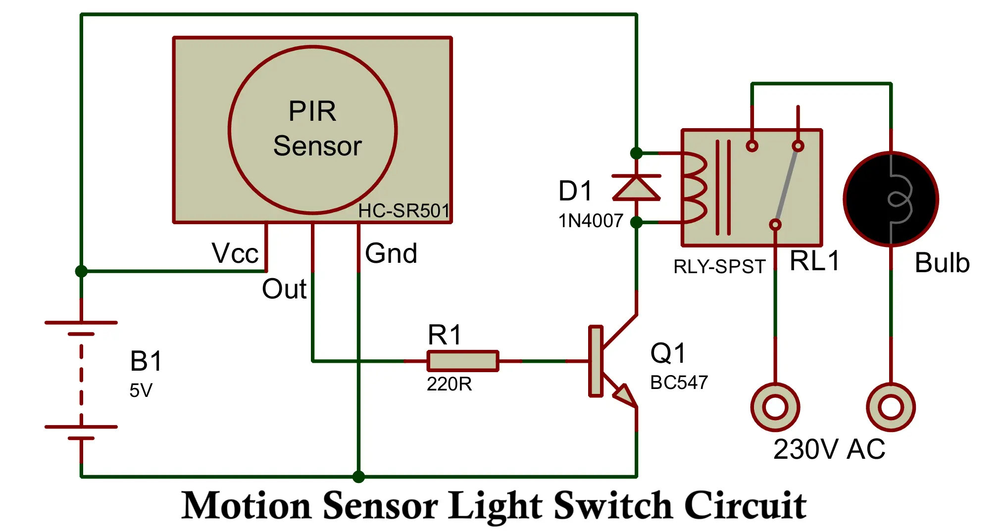
Motion Sensor Light Switch Circuit Diagram
Construction and Connections
- The PIR sensor has three pins — VCC, OUT, and GND.
- Connect VCC to +5V, GND to ground, and OUT to the base of the BC547 transistor through a 220Ω resistor.
- The collector of BC547 connects to one end of the relay coil, and the other end of the relay connects to +5V.
- The emitter of BC547 connects to ground.
- A 1N4007 diode connects across the relay coil terminals (cathode to +5V, anode to collector).
- The common (COM) and normally open (NO) contacts of the relay connects in series with the 220V AC bulb and AC phase line, so the bulb turns ON when the relay energizes.
- The neutral wire goes directly to the bulb.
You can assemble this motion sensor light circuit on a breadboard for testing or on a PCB for permanent installation. Place the PIR sensor in a suitable direction where it can detect human movement effectively (it has about 110° detection angle and 5–7 meters range).
Working of Motion Sensor Light Circuit
- PIR Sensor Detection
- The PIR sensor continuously monitors infrared radiation in its field of view.
- When a human or warm object moves within its range, the IR level changes, and the PIR sensor outputs a HIGH signal (around 3.3V).
- Transistor Activation
- This HIGH output applies to the base of BC547 through the 10kΩ resistor.
- The transistor gets forward biased and conducts current from the collector to the emitter.
- Relay Energization
- The conduction of BC547 energizes the relay coil, creating a magnetic field.
- This magnetic field closes the relay contacts (COM to NO).
- Bulb Turn ON
- The 220V AC circuit connected through the relay closes, and the bulb turns ON immediately.
- Automatic Turn OFF
- When no movement is detected, the PIR sensor output returns to LOW.
- The transistor switches OFF, de-energizing the relay, and the bulb turns OFF automatically after a short delay (set by the PIR module’s internal time-delay potentiometer).
The PIR sensor itself contains two small adjustable potentiometers:
- One for time delay (how long the output stays ON after detection).
- One for sensitivity (distance or motion detection range).
Advantages
- Energy Saving
- The light turns ON only when movement is detected, saving electricity.
- Automation and Convenience
- Fully automatic system; no need for manual switching.
- Enhanced Security
- It is useful as a security light that activates when someone enters the area.
- Low Power Consumption
- The PIR sensor consumes very little current (microamps in standby).
- Durability and Reliability
- Uses simple, robust components like transistor and relay with high reliability.
- Customizable
- Delay time and sensitivity can be adjusted as per need.
Disadvantages
- Limited Detection Range
- The PIR sensor’s range (typically 5–7 meters) might not cover large areas.
- False Triggering
- May trigger due to pets, hot air movement, or sunlight interference.
- Delay Adjustment Required
- Improper time-delay setting can cause frequent ON/OFF cycling.
- Indoor Limitation
- Not suitable for outdoor use unless waterproof housing is used.
- Needs Stable Power Supply
- Fluctuations in supply voltage may affect relay operation.
Applications
- Automatic Room Light Control
- Lights turn ON automatically when someone enters a room and turn OFF after they leave.
- Security Lighting Systems
- Used in outdoor and garage areas for automatic illumination during intrusions.
- Street and Garden Lights
- Can control street or garden lights to turn ON only when a person passes by.
- Automatic Washroom Light
- Lights operate automatically when someone enters the washroom.
- Industrial Automation
- Used in factories for energy-efficient lighting control in low-traffic areas.
- Smart Home Systems
- Integrated with microcontrollers or IoT modules for home automation projects.
Conclusion
The Motion Sensor Light Circuit using PIR Sensor, BC547, and Relay is a simple yet highly effective project for automatic lighting control. It blends energy efficiency, automation, and security in one compact system. With just a few inexpensive components, you can build an intelligent light controller that responds to human presence — ideal for smart homes, offices, and security systems.
By experimenting with the delay and sensitivity settings of the PIR sensor, you can fine-tune the system for various environments. It’s a perfect DIY project to learn about sensor-based automation and real-world electronic control.
4 Simple Clap Switch Circuits Using NE555 Timer, CD4017 IC & Transistors
Dual Power Supply Circuit ±(5V, 12V, 15V, 24V & 1.25V-30V DC)
BME680 and ESP8266 Based Indoor Air Quality Monitoring System