Dual power supply circuit is the backbone of many electronic systems. Various circuits, especially those involving operational amplifiers, analog devices, and certain digital systems, require both positive and negative voltages to operate properly. This is where Dual Power Supply Circuits come into play. They provide symmetrical voltages (like +12V and -12V, +15V and -15V, etc.) around a common ground, essential for many sensitive electronic applications.
In this article we will explore ±(5V, 12V, 15V, 24V and adjustable 1.25-30V) power supply with block diagram, working, advantages, disadvantages and applications.
What is a Dual Power Supply?
A dual power supply provides two output voltages: one positive and one negative with respect to a common ground. For example, a ±12V supply gives +12V, -12V, and 0V (ground). Many analog and mixed-signal circuits such as op-amps, analog sensors, and instrumentation systems require such dual rails.
Power Supply Block Diagram
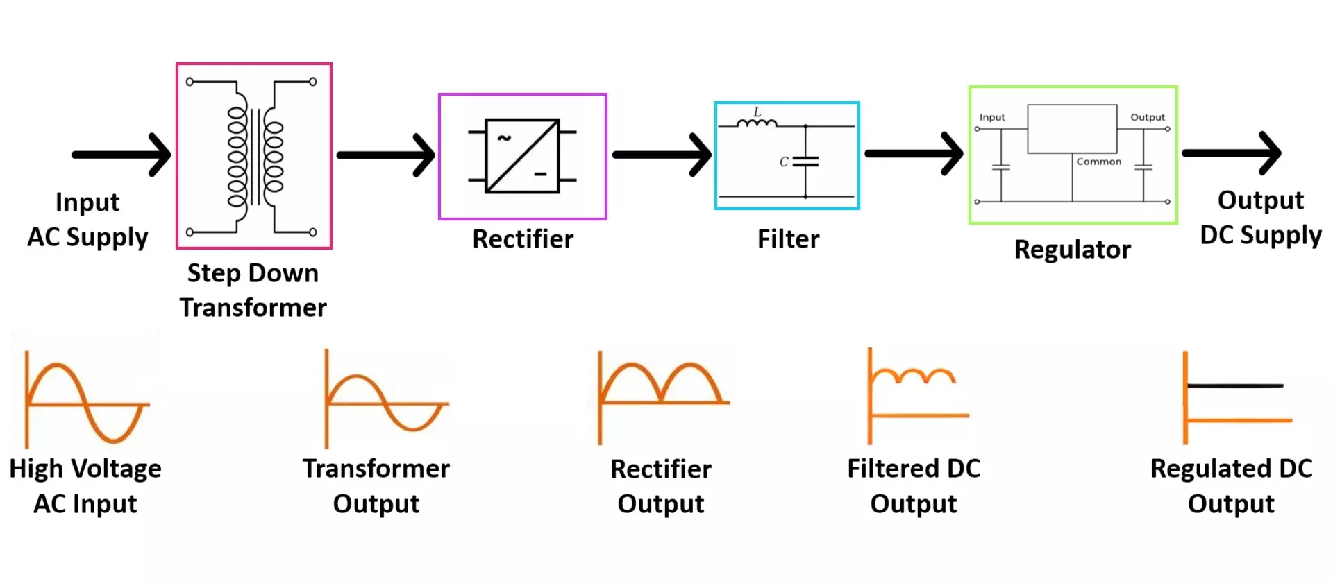
Components Breakdown:
- Transformer: Steps down AC voltage
- Rectifier: Converts AC to pulsating DC
- Filter Capacitors: Smoothens the DC
- Voltage Regulators: Provide fixed or adjustable positive and negative voltages
Working of a Dual Power Supply Circuit
- Step-Down Transformer:
- Converts high AC voltage (110V/230V) to a lower AC voltage (e.g., 15V-0-15V center-tap for ±12V supply).
- Bridge Rectifier:
- Converts AC to DC using diodes. Full-wave rectification utilizes both halves of the AC waveform.
- Filtering:
- Large electrolytic capacitors filter the rectified DC to reduce ripple voltage.
- Voltage Regulation:
- Uses IC regulators (like 7805, 7812 for positive and 7905, 7912 for negative rails) to maintain constant output voltage.
- Adjustable regulators like LM317 (positive) and LM337 (negative) allow output voltage adjustment.
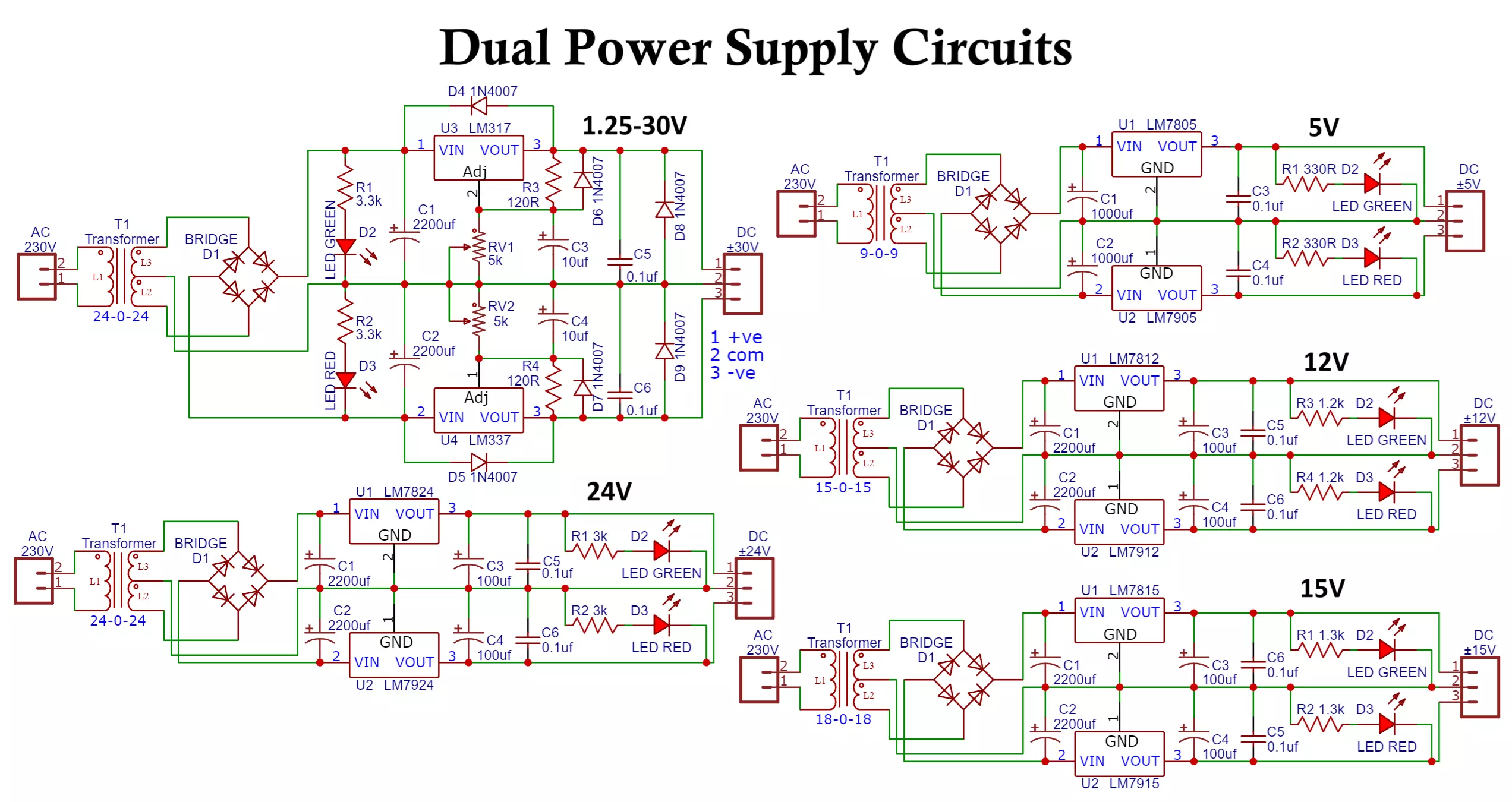
Fixed Dual Power Supply Circuits
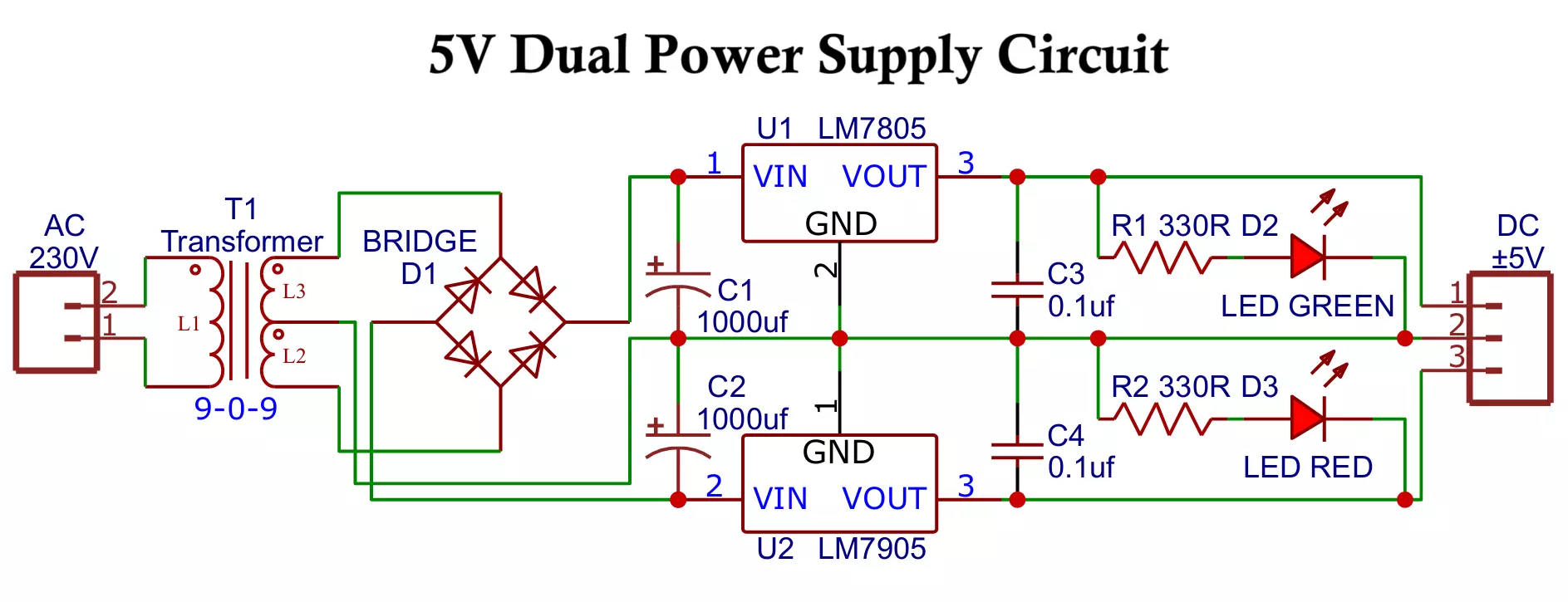
A. Fixed ±5V Dual Power Supply Circuit
Components:
- Transformer: 9-0-9V 2A
- Rectifier: 4 diodes or integrated bridge rectifier
- Regulators: 7805 (positive), 7905 (negative)
- Capacitors: 1000μF x2 filtering + 0.1μF x2 bypass
- Two LEDs (Red and Green) with 330Ω resistor
- 2 pin and 3 pin 5 mm screw terminals
Circuit Diagram:
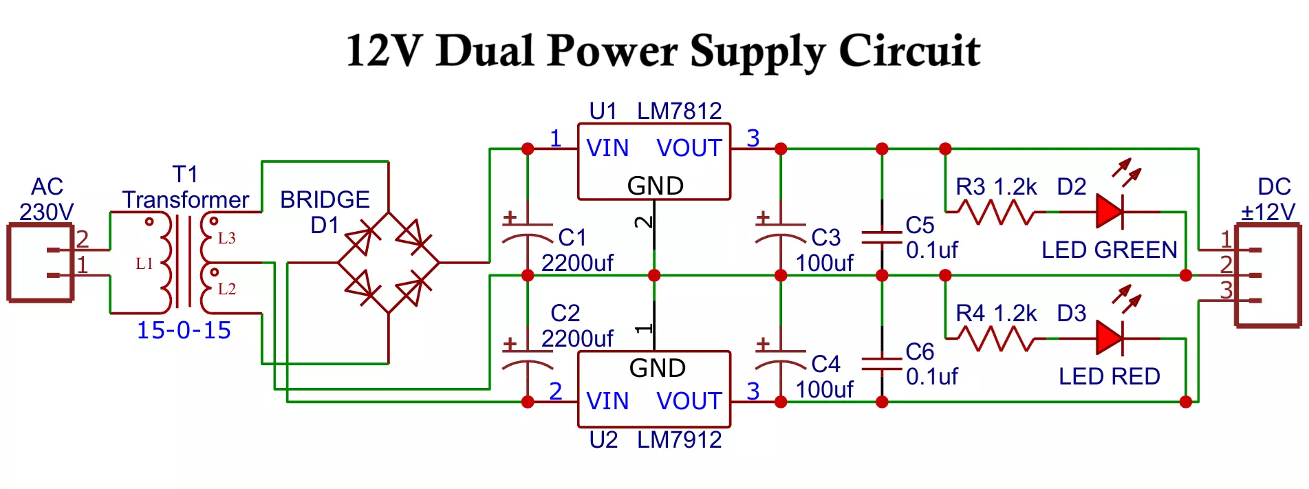
B. Fixed ±12V Dual Power Supply Circuit
Components:
- Transformer: 15-0-15, 40VA
- Rectifier: 4 diodes or integrated bridge rectifier
- Voltage Regulators: LM7824, LM7924
- Capacitors: 2200μF x2 and 100μF x2 35V electrolytic + 0.1μF x2 ceramic
- Two LEDs (Red and Green) with 1.2 to 1.5kΩ resistor
- 2 pin and 3 pin 5 mm screw terminals
Circuit Diagram:
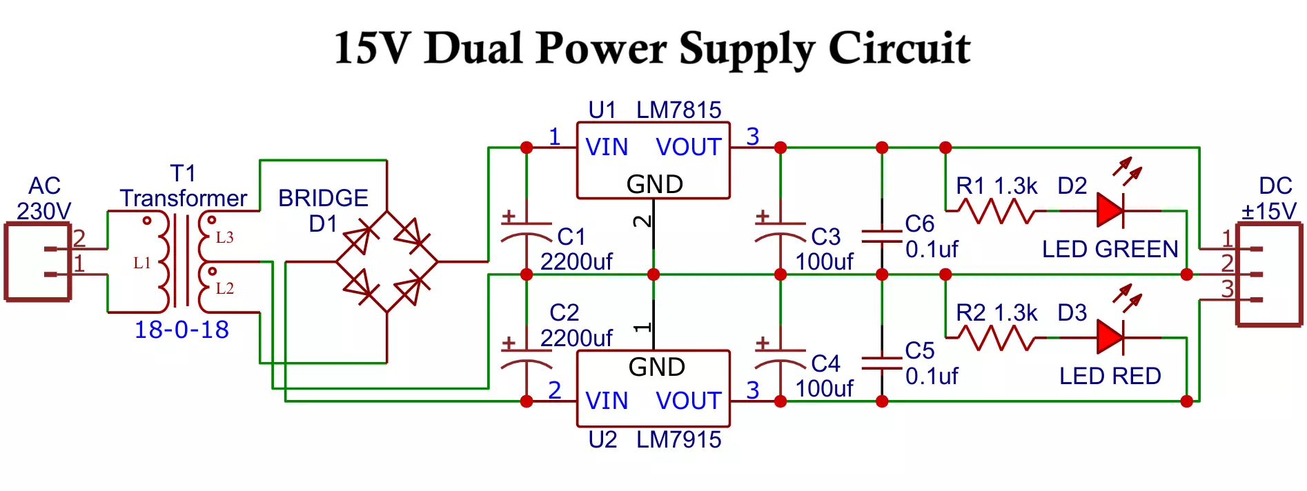
C. Fixed ±15V Dual Power Supply
Components:
Similar to the ±12V design but use:
- Transformer: 18-0-18V
- Rectifier: 4 diodes or integrated bridge rectifier
- Voltage Regulators: LM7815, LM7915
- Capacitors: 2200μF x2 and 100μF x2 50V electrolytic + 0.1μF x2 ceramic
- Two LEDs (Red and Green) with 1.3 to 1.5kΩ resistor
- 2 pin and 3 pin 5 mm screw terminals
Circuit Diagram:
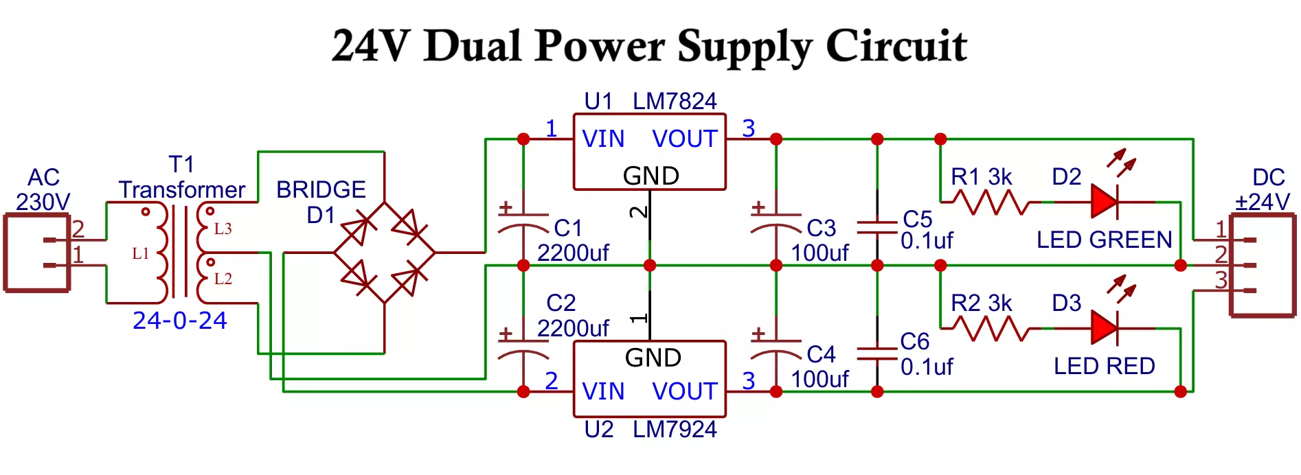
D. Fixed ±24V Dual Power Supply
Components:
- Transformer: 24-0-24
- Rectifier: 4 diodes or integrated bridge rectifier
- Voltage Regulators: LM7824, LM7924
- Capacitors: 2200μF x2 and 100μF x2 50V electrolytic + 0.1μF x2 ceramic
- Two LEDs (Red and Green) with 3kΩ resistor
- 2 pin and 3 pin 5 mm screw terminals
Circuit Diagram:
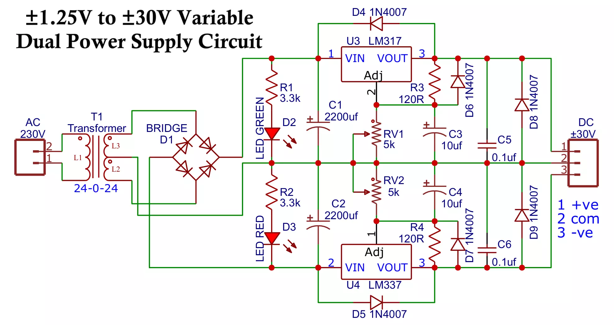
Variable Dual Power Supply with LM317 and LM337 Regulators
Components:
- Transformer: 24-0-24V 60- 80VA
- Rectifier: 4 diodes or integrated bridge rectifier
- Two LEDs (Red and Green) with 3.3kΩ resistor
- Capacitors: 2200μF x2 and 10μF x2 50V electrolytic + 0.1μF x2 ceramic
- Voltage Regulators: LM317 (positive adj.) and LM337 (negative adj.)
- Potentiometers: 5k x2 for voltage adjustment
- Resistor: 120Ω
- Protection Diodes: 1N4007 x6
- 2 pin and 3 pin 5 mm screw terminals
Circuit Diagram:
Output Calculation (for LM317/337):

Vout = 1.25V × (1 + R2/R1) + Iadj × R2
Typically, Iadj is small and can be neglected.
A simple, effective variable ±1.25 to ±30V dual power supply based on the LM317 and LM337 three-terminal adjustable regulator ICs. While it’s not intended for high-current power delivery, it is more than adequate for powering and testing preamps, audio circuits, analog signal chains, and even power amplifiers (as long as no speaker load is connected during testing).
The complete circuit is straightforward, but several important details ensure safe, reliable, and stable operation.
Transformer Selection
This version uses a 24-0-24V, 60–80VA transformer, which provides about ±33V DC after rectification and filtering:
VDC ≈ 24V × √2 – 1.4V ≈ 32.5V
This voltage is well-suited for achieving adjustable outputs up to ±30V. However, as it approaches the maximum input voltage limit of the LM317/LM337 (around 40V), care must be taken to prevent voltage surges or overheating. Use 50V-rated capacitors and ensure solid thermal management.
Heatsinking the Regulators
The LM317 and LM337 will shut down if they overheat, which not only disrupts testing but may shorten lifespan. Mount both regulators on suitable heatsinks, using proper electrical insulation kits (mica or silicone pads + insulating washers).
Wiring Considerations
- Keep regulator wiring as short as possible.
- Ensure that the regulators are mounted within 100mm of the main filter capacitors (C1 and C2) to avoid oscillation.
- If longer wiring is required, place the 10µF electrolytic capacitors directly at the regulator input pins for local stabilization.
- 0.1µF ceramic capacitors should also be installed close to both input and output terminals to improve high-frequency performance.
- 5k potentiometers are used to set the output voltage and can be mounted remotely without affecting stability.
Diode Protection
Use 1N4007 diodes for robust protection throughout:
- D1 the bridge rectifier (an integrated bridge module).
- D4 and D5 are placed across the output and input of each regulator to prevent damage from large output capacitors discharging back into the regulator.
- D6 and D7 are connected between the adjust pin and output to protect the internal reference circuitry from reverse conditions.
- Always verify polarity before powering on.
Filtering and Bypass Capacitors
- Use two 2200µF / 50V electrolytic capacitors (C1, C2) for filtering the positive and negative rails.
- 10µF electrolytics (C3, C4) and 0.1µF ceramics (C5, C6) provide local decoupling at the regulators and improve transient response.
- Larger electrolytics (e.g., 4700µF or more) can be used but offer diminishing returns beyond ~10,000µF total.
Output Voltage Control
- 5k linear potentiometers (one per regulator) allow you to fine-tune output voltage.
- A fixed 120Ω resistor is used in the voltage-setting divider for each regulator (per LM317/LM337 design standards).
- This setup allows an output range from approximately ±1.25V to ±30V, depending on the adjust resistor ratio.
Connectors and Indicators
- Use 2-pin and 3-pin screw terminals (5 mm pitch) for easy, secure wiring.
- Include two LEDs (Red and Green) with 3.3kΩ resistors as power indicators for the +V and –V rails.
- Ensure LEDs are connected after regulation, not directly to unregulated DC.
Operation & Testing
- Before connecting any circuit, set the output voltage to minimum using the potentiometers.
- Power on, then slowly increase voltage while monitoring current draw.
- Check for regulator heating excessive dissipation means your load may be drawing too much current or your input voltage is too high.
- Confirm stable operation with both positive and negative outputs under load.
This power supply delivers a clean, adjustable ±1.25V to ±30V output and is well-suited for Audio preamps, Op-amp test setups, Signal conditioning circuits
With a 24-0-24V transformer, LM317/LM337 regulators, and well-considered protection and filtering, this design provides a robust and flexible solution for analog and low-power electronics development.
Practical Tips for Building Dual Power Supplies
- Heat Dissipation: Use heatsinks on regulators.
- Protection: Add fuses, MOVs, and protection diodes.
- Ripple Voltage: Use high-quality electrolytic capacitors to reduce ripple.
- Transformer Rating: Ensure sufficient current capability.
- Load Testing: Always test under load to verify voltage stability.
- Wire Size: Use proper gauge wires to handle current.
- LEDs: Consider adding indicator LEDs to monitor power rails.
Safety and Grounding
- Always insulate all mains AC connections with heat-shrink or insulating sleeves.
- The metal chassis should be earth-grounded per local electrical codes.
- Keep the DC ground (GND) floating from the chassis ground to avoid ground loops during testing with other audio or analog equipment.
Advantages of Dual Power Supply
- Can power both positive and negative voltage circuits.
- Essential for operational amplifiers and analog designs.
- Improved stability for signal processing circuits.
- Provides symmetrical rails for balanced circuit operation.
Disadvantages of Dual Power Supply
- More complex than single-supply designs.
- Requires center-tap transformers which can be bulkier.
- Higher component count increases cost and size.
- Heat management needed for regulators.
Applications of Dual Power Supply
- Operational Amplifier Circuits
Dual supplies (+V and –V) allow op-amps to process both positive and negative portions of input signals, essential for amplification, filtering, and signal conditioning. - Analog Signal Processing
Enables circuits to handle full-range AC signals, which swing above and below ground, without distortion or signal clipping. - Audio Equipment
Used in audio preamps, equalizers, and power amplifiers to deliver clean sound and maintain symmetry in waveform reproduction. - Data Acquisition Systems
Powers analog front-ends and sensor interfaces that produce bipolar outputs, improving signal accuracy and resolution. - Communication Devices
Supports analog RF stages, modulators, and demodulators requiring symmetrical power rails for proper signal handling. - Medical Electronics
Provides the precision required in devices like ECGs and EEGs for accurate amplification of tiny bio-signals, which can be both positive and negative. - Industrial Control Systems
Used in process control instruments and analog input/output modules that manage real-world signals, many of which are bipolar. - Laboratory Power Supplies
Bench power supplies often include dual outputs to support a wide range of analog and mixed-signal circuit prototyping. - Differential Amplifiers
Necessary for amplifiers that measure voltage differences, allowing output to swing in both directions relative to ground. - ADC/DAC Interfaces
Some analog-to-digital and digital-to-analog converters require dual supplies to accurately process bipolar signals.
Conclusion
A Dual Power Supply is crucial for many modern electronic designs, particularly where analog signals are processed. Whether you need a fixed ±12V for op-amps or an adjustable ±2-35V supply for lab testing, the principles remain the same. Proper design ensures reliability, stability, and long service life for the end application.
Types of Dual Power Supplies
| Output Voltage | Transformer Rating | Regulator ICs | Application |
|---|---|---|---|
| ±5V | 9-0-9V | 7805, 7905 | Logic Circuits |
| ±12V | 15-0-15V | 7812, 7912 | Op-amps, Audio |
| ±15V | 18-0-18V | 7815, 7915 | Analog, Instrumentation |
| ±24V | 24-0-24V | 7824, 7924 | Industrial Automation |
| ±1.25V to ±30V | 24-0-24V | LM317, LM337 | Lab power supplies |
Half and Full Bridge LLC Resonant Converter Circuit Explained