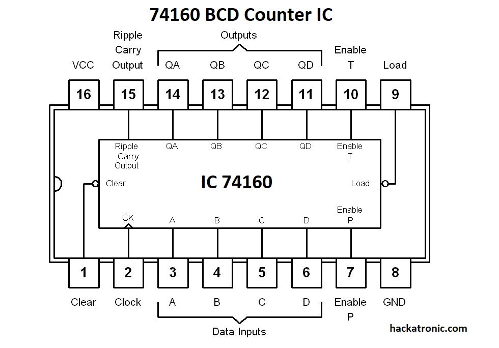
In this article, we will see 74160 IC you can see 74160 BCD Counter Circuit Diagram. It is a 16 pin BCD counter with a feature of count loading means it is presettable. That means if you want you can count from anywhere between 0 to 9. It is a positive edge triggered IC.
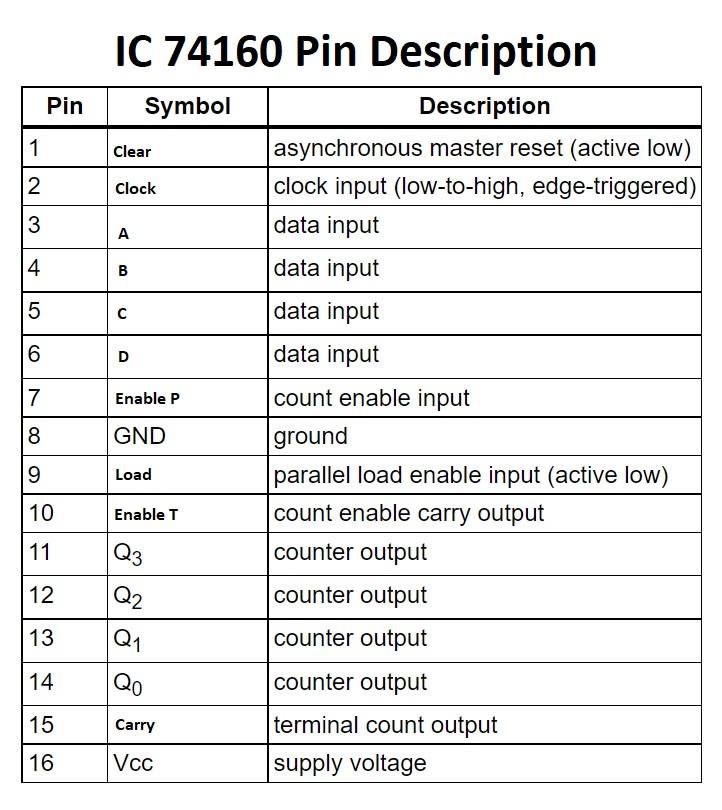
Pin Description of IC 74160:
By using the A, B, C, and D data input pins we can set the output pins QA, QB, QC, and QD to high or low. The active-low clear input resets the IC to 0000. The load enables input (P) enables the count. load input loads data inputs to counter on the positive edge of the clock. Pin 15 is the ripple carry output of this IC, it makes it very easy to cascade multiple ICs to get a higher count.
Features:
- Synchronous counter with the feature of loading
- Two counts enable inputs for n-bit cascading
- Asynchronous reset
- Positive-edge triggering
MOD 7 Counter using 74160 IC:
IC 74160 can be converted into a MOD counter by modifying the circuit.
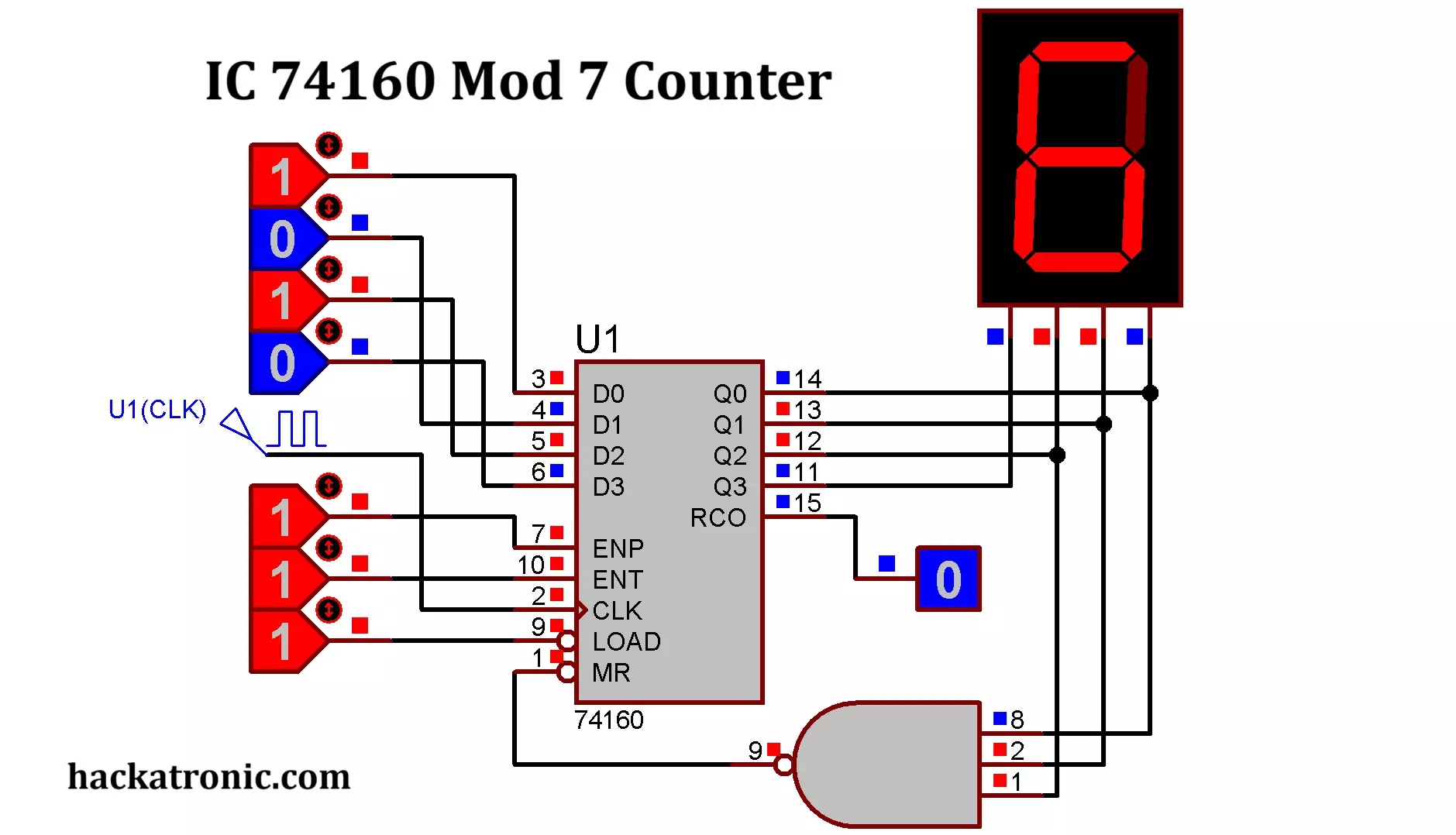
We have connected a three-input NAND gate to the outputs of 74160 IC. The output of the NAND gate remains High and when the count output becomes 111 that is 7 it immediately reset the IC. count 7 is not shown on display. Only 7 numbers from 0 to 6 are displayed on the screen hence it is a MOD 7 counter.
74160 BCD Counter Circuit Diagram:
What is BCD? BCD stands for Binary Coded Decimal. After number 9 to represent 10 (0001 0000) we represent 0 by four zeros and a 1 which means there is no hexadecimal count from 0000 to 1111 for it. IC74160 is useful in decimal counting.
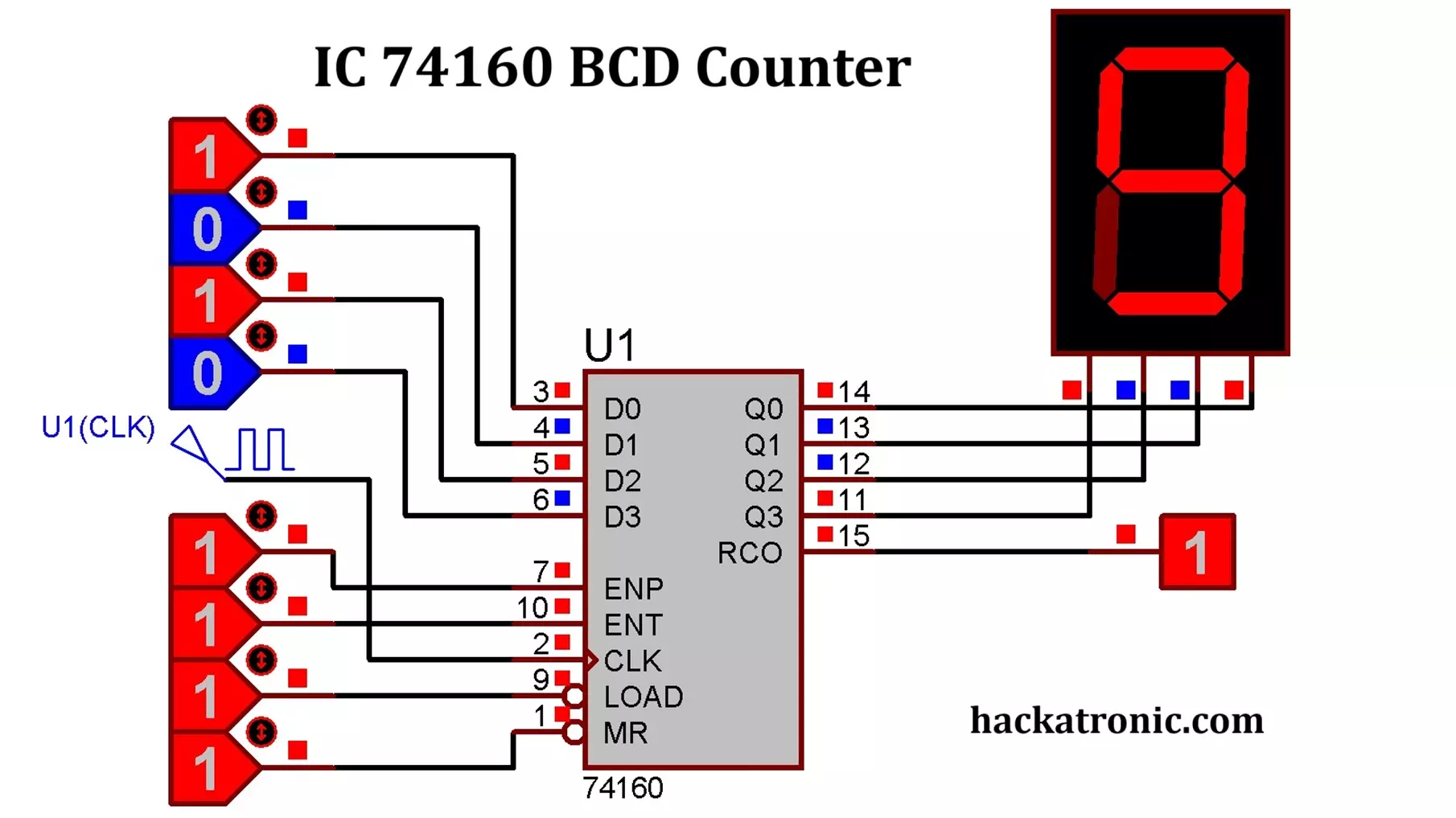
Above is the circuit diagram of the IC 74160 BCD counter. Pins D0 to D3 are not in use, so we will not connect them. A clock input of 2Hz is given at pin 2, pin 1, 10, 7, 9 are connected to logic High. Q0, Q1, Q2, Q3 are connected to the 7 Segment display. This counter counts from 0 to 9 in BCD.
IC 74160 BCD Counter Circuit
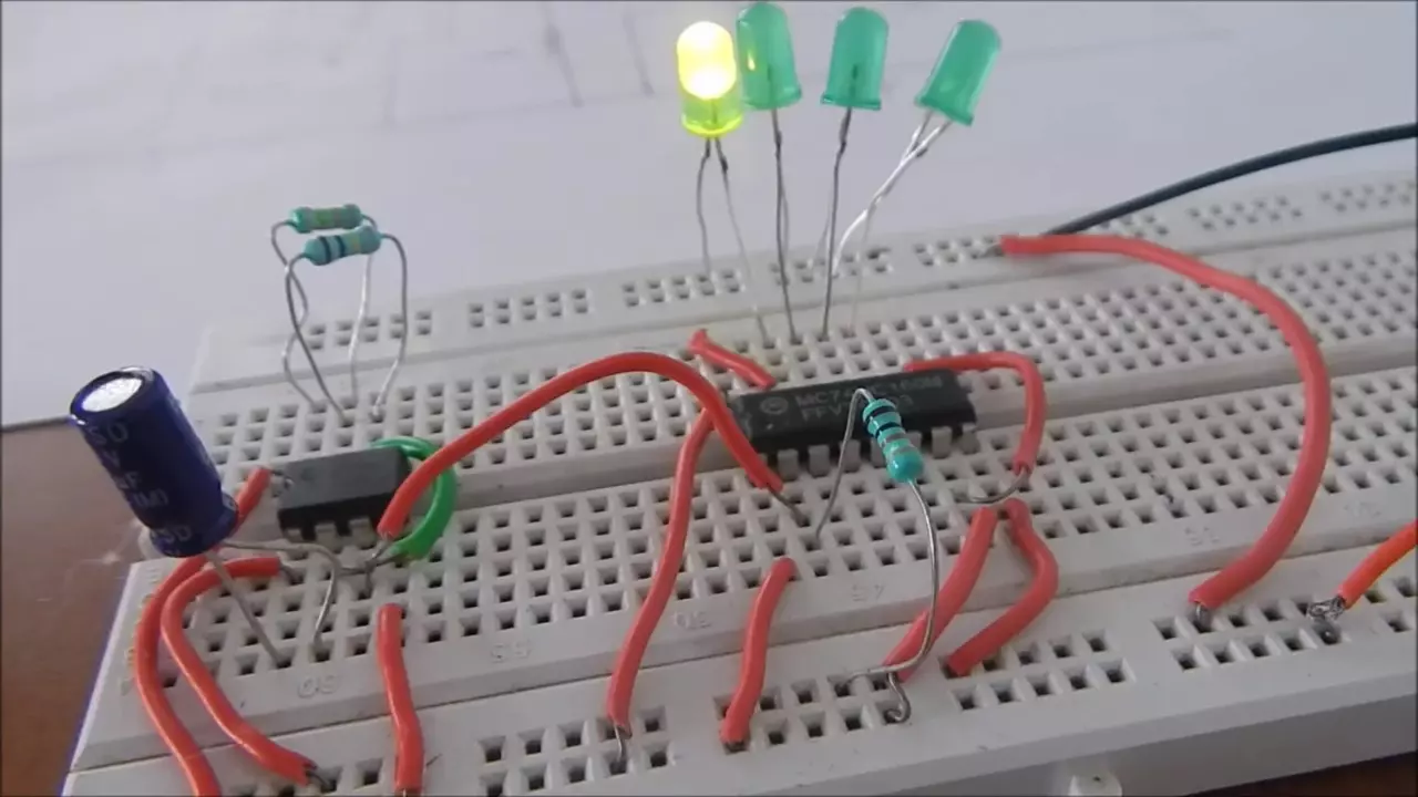
Here is how we have implemented this circuit on a breadboard. We have used a 555 timer IC to provide a clock pulse. To show the output we have used 4 Green colored LEDs.
Components Required:
- 74160 IC
- 555 Timer (as clock generator)
- 4 LEDs (for output display)
- Resistors (1KΩ, 330Ω)
- Capacitors (for debounce)
- Power supply (+5V)
Connections:
- Connect VCC (Pin 16) to +5V and GND (Pin 8) to Ground.
- Connect a 555 Timer circuit to provide a clock signal to CP (Pin 2).
- Connect Q0-Q3 (Pins 11, 12, 13, 14) to LEDs via 330Ω resistors.
- Tie MR (Pin 1) to HIGH (to avoid reset).
- Connect Load (Pin 9) to HIGH (to allow counting).
- Connect a push-button to MR for manual reset.
Working of 74160 MOD 10 BCD Counter
The 74160 operates as a synchronous counter, meaning all four flip-flops inside it are clocked simultaneously. The operation follows these steps:
Counting Mode
- When Load = HIGH and Master Reset (MR) = HIGH, the counter increments on each positive edge of the clock (CP).
- It counts in BCD format from 0000 (0) to 1001 (9).
- After reaching 1001 (9), the next clock pulse resets it back to 0000 (0) automatically.
Reset Function
- If MR = LOW, the counter immediately resets to 0000 (0), regardless of the clock signal.
Preset/Load Function
- If Load = LOW, the counter loads the value given on D0-D3 inputs.
Terminal Count (TC) Output
- The RCO output goes HIGH when the counter reaches 1001 (9).
- This signal is useful for cascading multiple counters.
Applications of IC 74160 BCD Counter
- Digital Clocks: Used in seconds and minutes counting in digital clocks.
- Frequency Counters: Counts pulses from a signal source to determine frequency.
- Timer Circuits: Used in countdown timers and event counters.
- Automatic Numbering Systems: Used in electronic voting machines (EVMs) and scoreboards.
- LED Chasers: Used to create cascading LED effects.
- Industrial Automation: Used in production line counters to keep track of manufactured units.
Conclusion
The 74160 MOD-10 BCD Counter is a versatile IC used in many digital applications where decimal counting is required. Its synchronous design ensures accurate counting without timing glitches. I hope this was helpful to you comment down if you have any queries.