Voltage controlled oscillator circuit is an electronic oscillator circuit whose output frequency is controlled by an input voltage source. By varying the input voltage, we can change the output frequency. A voltage controlled oscillator can produce frequencies ranging from few Hertz to tens of Gigahertz.
Voltage to frequency converters is used in frequency modulation FM and phase modulation PM. VCO is used in phase lock loop circuits.
Voltage controlled oscillators are classified into two groups depending upon the waveform they produce as output.
1. Harmonic Oscillator:
A harmonic oscillator generates a sinusoidal waveform. Some of the examples are LC tank oscillators and crystal oscillators.
2. Relaxation Oscillator:
Relaxation oscillator generates a triangle or a sawtooth waveform. They are generally used in IC to provide a wide variety of frequencies.
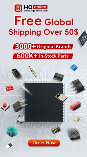
Here we will discuss a simple circuit to make a voltage controlled oscillator. Here we are generating a triangle wave by continuously charging and discharging a capacitor in an automated way. The charging of the capacitor is controlled by the voltage source which decides how much fast the capacitor will get charged.
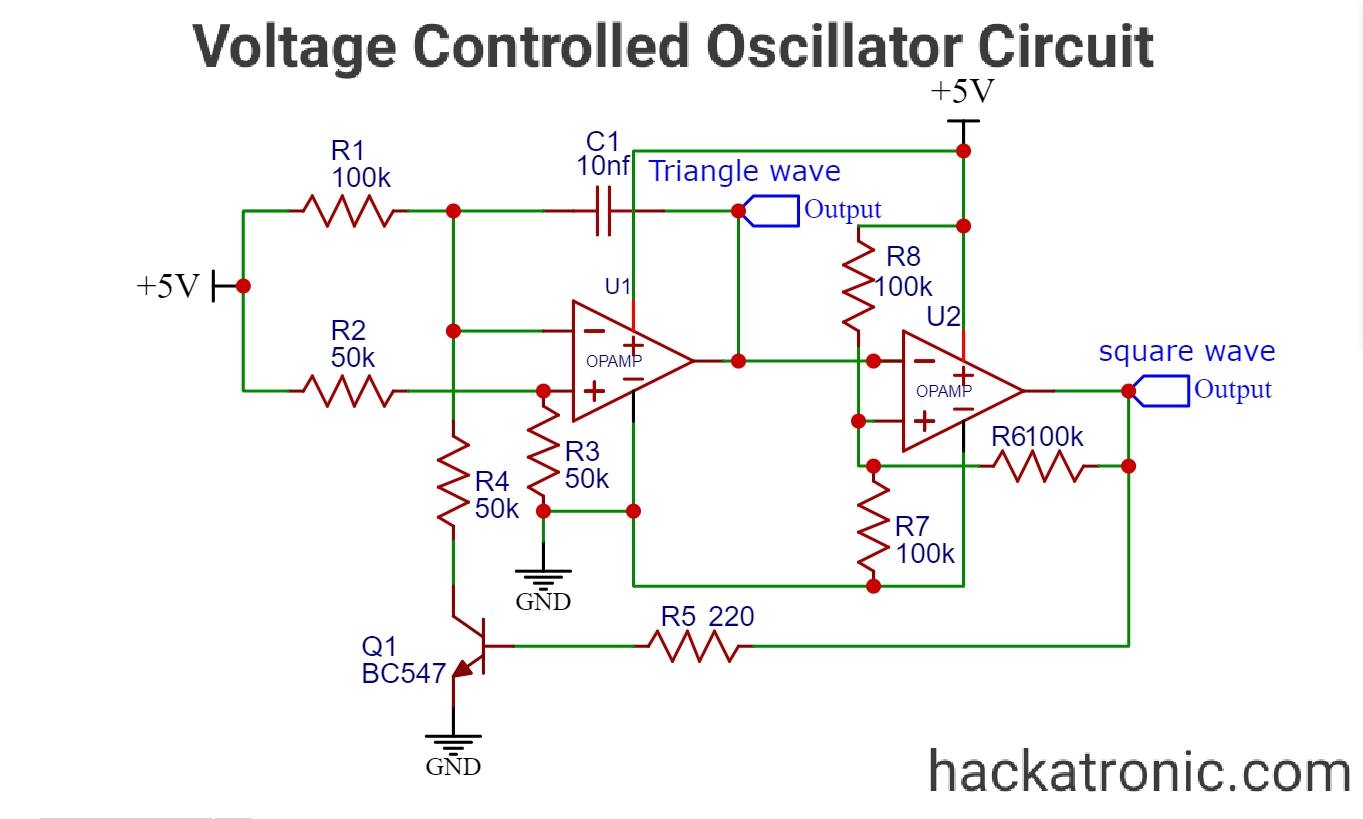
In this circuit, there are two OPAMPs the first one is to make the triangle wave and the second one to make a square wave. A transistor is used to discharge the capacitor via the resistance R4.
Let’s understand the working of this circuit
A. When the transistor is OFF:
The capacitor gradually charges through resistor R1. A voltage divider circuit is used to make a reference voltage at the non-inverting terminal of the opamp. The capacitor is connected to the feedback path of the circuit. At the output of the first OPAMP, we get a triangle wave.
B. When the transistor turns to ON state:
The output of the first OPAMP is given to the second opamp which acts as a comparator and generates a square wave. Also, this opamp switches the transistor. This opamp is nothing but the Schmitt trigger.
When the signal at its inverting terminal is low the output is high which keeps the transistor ON and discharges the capacitor through the resistor R4. When the signal at the inverting terminal is high with respect to the threshold voltage, output goes low making the transistor OFF.
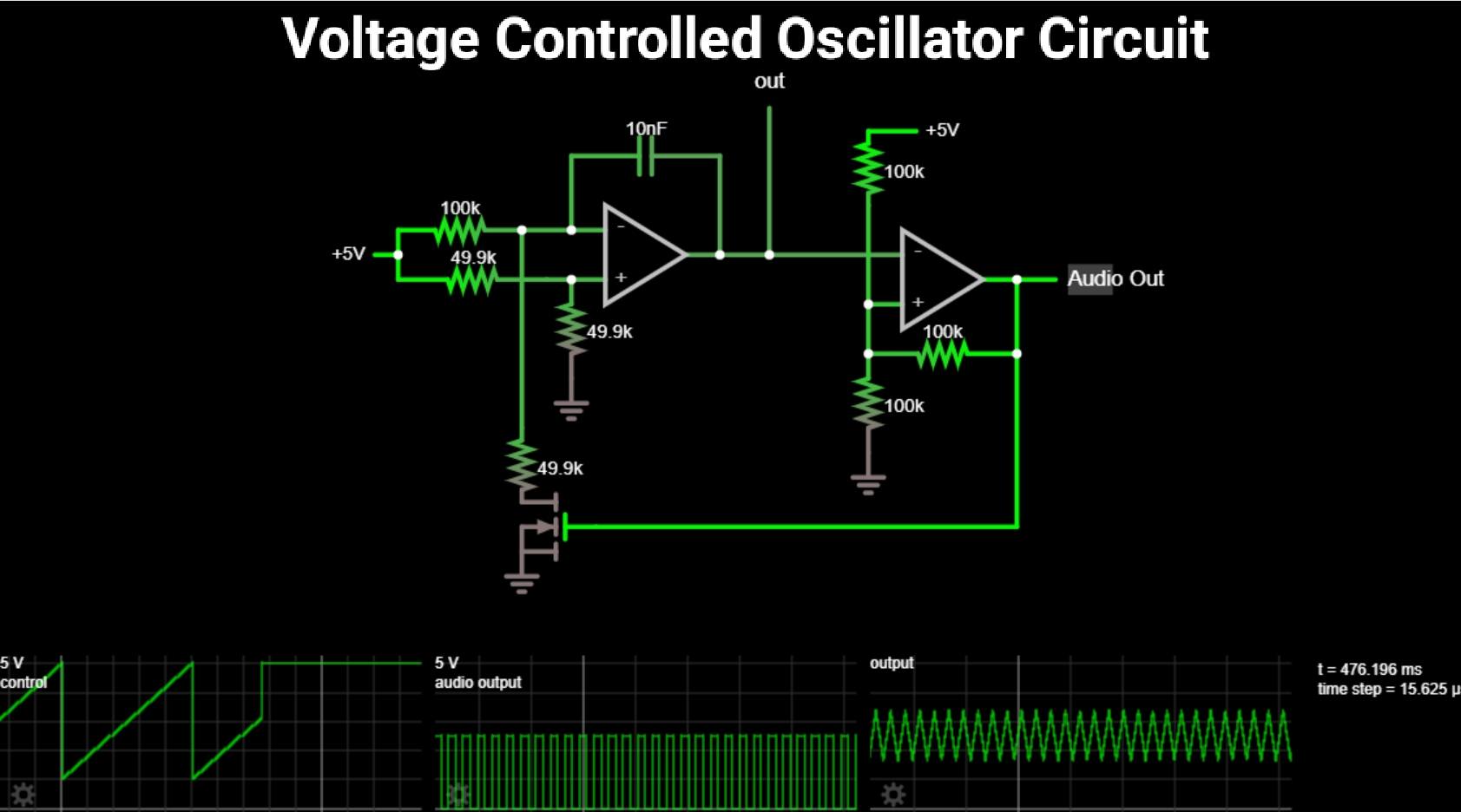
IC 566 voltage-controlled oscillator:
FEATURES of 566 VCO:
- 566 VCO is an 8 pin IC, it can operate between 10 to 24 volts.
- High linearity of modulation
- stable center frequency
- Highly linear triangle wave output
- Frequency programming using a resistor or capacitor voltage or current.
- Frequency adjustable over 10-to-1 range with the same capacitor.
- 0˚C to 70˚C operation temperature range.
Applications of voltage-controlled oscillator circuit:
- Tone generators
- Frequency shift keying
- FM modulators
- Clock generators
- Signal generators
- Function generators
- Electronic jamming circuit
LM566 is a general-purpose voltage controlled oscillator whose output frequency depends on the applied input voltage. It generates a triangle wave and a square wave as a function of the input voltage.
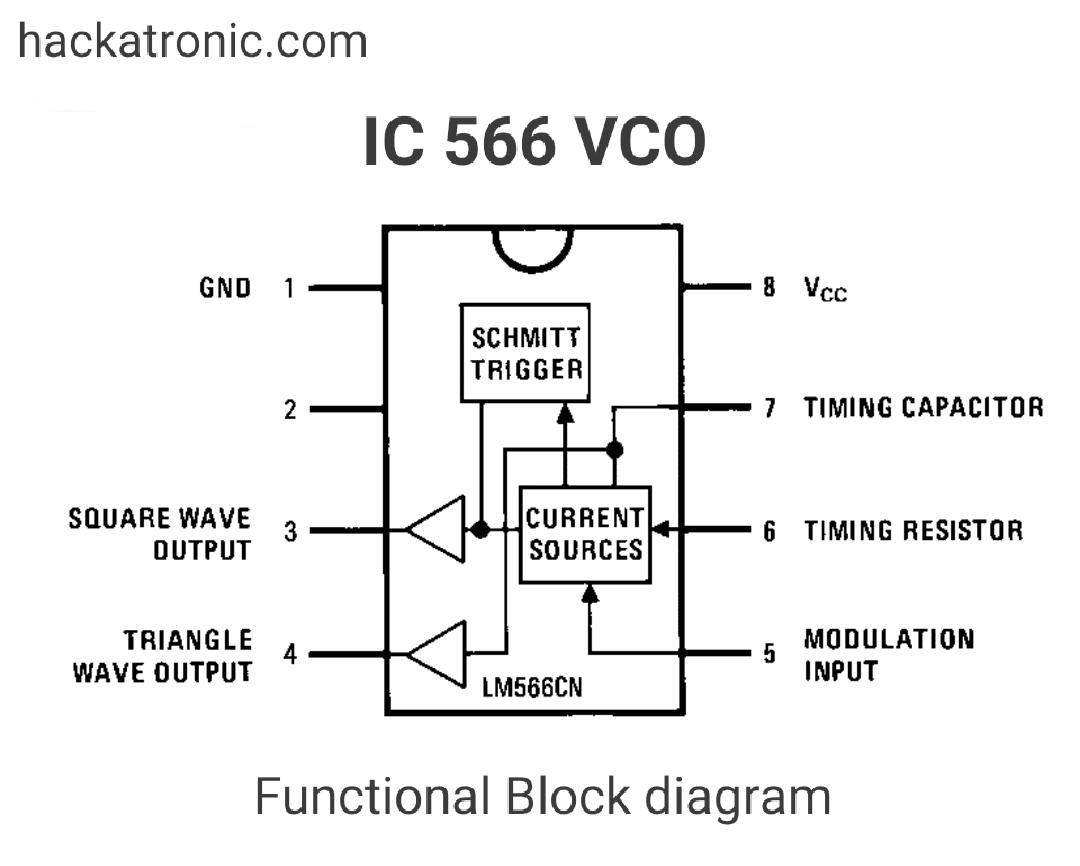
Pin Description of LM566:
1: Ground (GND)
2: No connection (NC)
3: Square wave output
4: Triangular wave output
5: Modulation input
6: Timing resistor
7: Timing capacitor
8: Vcc
Working of NE566 Voltage controlled oscillator circuit:
The LM566 actually contains a current source a Schmitt trigger and two buffer amplifiers.
The current source charges and discharges the external capacitor depending on the value of the timing resistor and input voltage. At the terminal of the capacitor, we get a triangle wave. This triangle wave is then given as output via a buffer amplifier at pin 4.
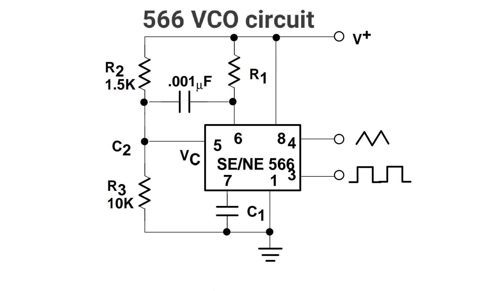
A 1nf capacitor is connected between pins 5 and 6. A Schmitt trigger is used to switch the charging and discharging of the capacitor. The Schmitt trigger also compares the triangle wave against a reference voltage to produce a square wave. This square wave is given as output at PIN 5.
Must read triangle wave generator using opamp
The magnitude of the triangular wave and the square wave is about 2.4Vpeak to peak and 5.4Vpeak to the peak.
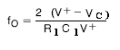
The free-running or center-operating frequency, fo is given by the expression:
Phase lock loop PLL:
A phase lock loop is based on voltage controlled oscillator. It is used to lock the output of a voltage controlled oscillator with respect to the input frequency. It continuously compares the phase of output frequency with the input frequency. The output is continuously adjusted until it matches the input frequency.
The PLL is used for generations, modulation, and demodulation of a signal. They are used in frequency and amplitude modulation.
Working of Phase Locked Loop:
In the above block diagram, Phase detector PD compares the output frequency with the input reference frequency. When an error occurs, the phase detector generates an error signal. It is filtered using a low pass filter to remove the noise and this signal is applied to the VCO to generate the output frequency. This output frequency is given to the phase detector via a divide by N counter which divides the output frequency by a certain number N and gives it to the phase detector. This entire process works in a loop hence it is called a phase lock loop. LM567 is a PLL that is used as a tone decoder.